
Annular steel-steel support connecting joint structure for steel structure and externally-hung wall plate

A technology for hanging wall panels and connecting nodes, which is applied in building structure, building components, earthquake resistance, etc., can solve the problem of not being used in large quantities, and achieve the effect of speeding up the construction progress, saving labor costs, and saving maintenance costs.

Pending Publication Date: 2021-04-16
SOUTH CHINA UNIV OF TECH
View PDF1 Cites 4 Cited by
  • Summary
  • Abstract
  • Description
  • Claims
  • Application Information

AI Technical Summary

Problems solved by technology

However, in the current existing implementation plans, U-shaped steel plates are mainly used for the connection between wall panels, and are rarely used for the connection between wall panels and steel frames (Hou Hetao, Qian Yiqiao, Xie Surong. For prefabricated U-shaped steel-frictional energy-dissipating nodes and external wall system for external wall panels [P]. Shandong Province: CN111519786A, 2020-08-11.); the research on low-yield steel dampers is mainly concentrated on the component level, and has not been widely used in In actual engineering

Method used


Image

  • Annular steel-steel support connecting joint structure for steel structure and externally-hung wall plate
  • Annular steel-steel support connecting joint structure for steel structure and externally-hung wall plate
  • Annular steel-steel support connecting joint structure for steel structure and externally-hung wall plate

Examples


Embodiment Construction

[0029] The purpose of the invention of the present invention will be described in further detail below in conjunction with the accompanying drawings and specific embodiments, and the embodiments cannot be repeated here one by one, but the implementation of the present invention is not therefore limited to the following embodiments. Unless defined otherwise, all technical and scientific terms used herein have the same meaning as commonly understood by one of ordinary skill in the art to which this application belongs.

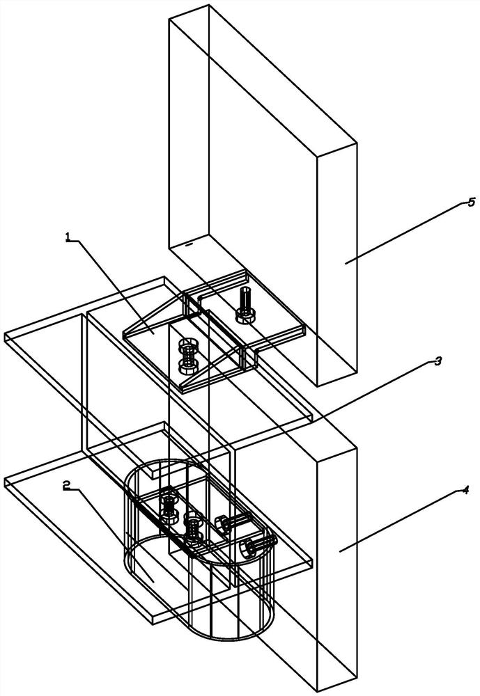
[0030] Such as figure 1 and Figure 4 As shown, the ring-shaped steel-steel bracket connection node structure used for the steel structure and the external wall panel includes the lower external wall panel 4 and the upper external wall panel 5, and the lower external wall panel 4 is connected to the upper external wall panel through the frame beam 3 The plate 5 is connected, and the frame beam 3 is provided with an upper node connection device and a lower node ...


PUM

PropertyMeasurementUnit
Thicknessaaaaaaaaaa
Diameteraaaaaaaaaa

Abstract

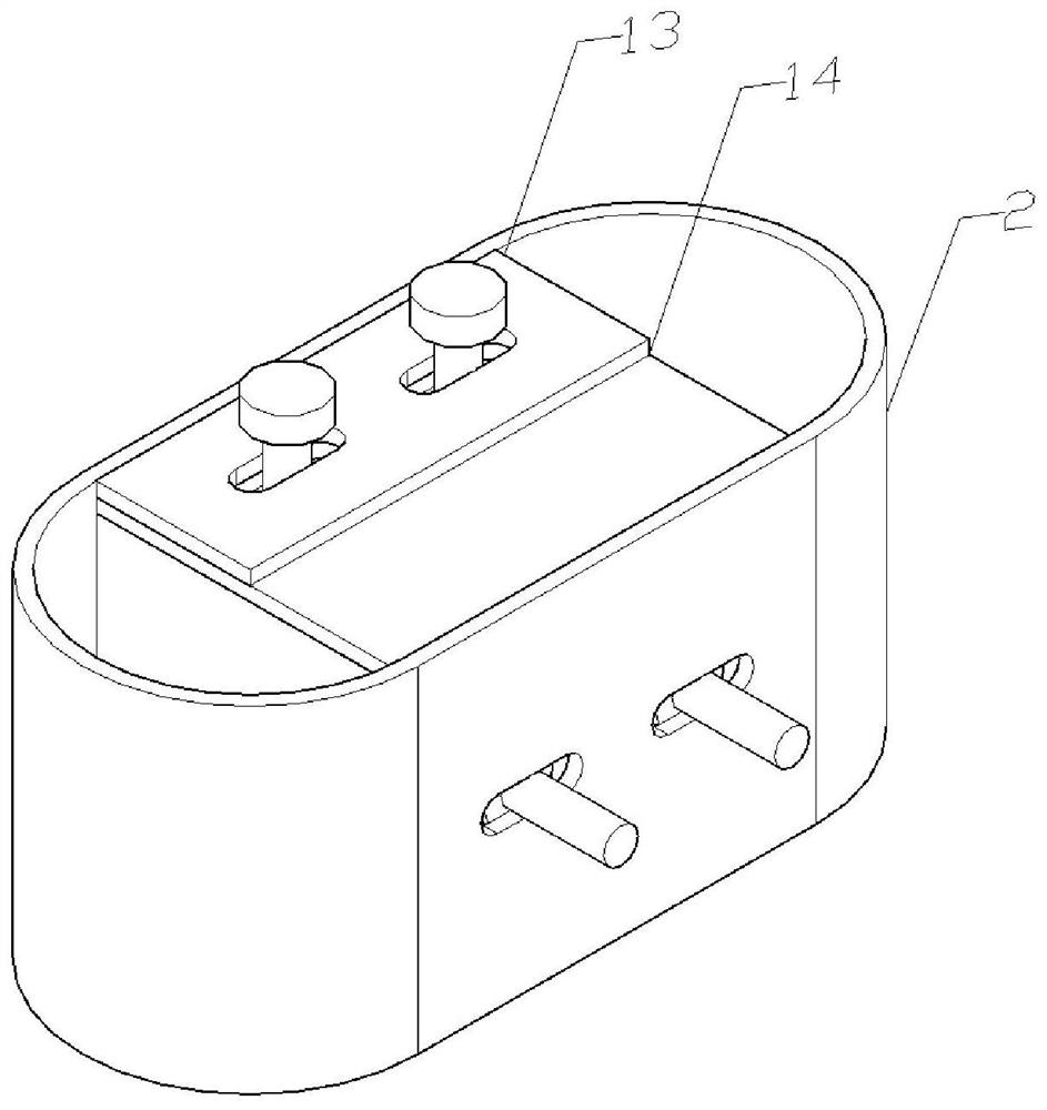
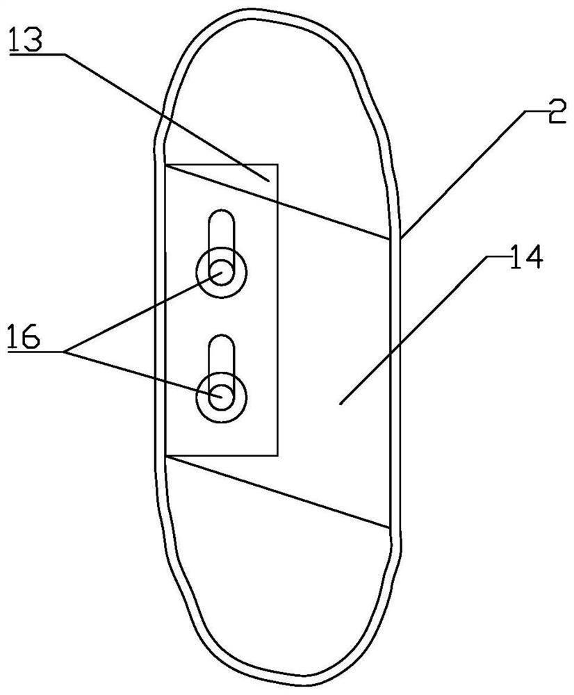
The invention discloses an annular steel-steel support connecting joint structure for a steel structure and an externally-hung wall plate. The annular steel-steel support connecting joint structure comprises a lower-layer externally-hung wall plate and an upper-layer externally-hung wall plate, the lower-layer externally-hung wall plate is connected with the upper-layer externally-hung wall plate through a frame beam, and the frame beam is provided with an upper joint connecting device and a lower joint connecting device; the upper joint connecting device comprises an upper joint annular steel plate, a connecting steel plate and an embedded part; at least more than one energy dissipation steel sheet is arranged on the upper joint annular steel plate; the connecting steel plate is located on the inner surface of the upper joint annular steel plate and makes contact with a lower flange of the frame beam; the embedded part is located in the lower layer externally-hung wall plate and connected with the upper joint annular steel plate; and the embedded part comprises a bolt sleeve, an anchoring steel bar and an embedded part steel plate, the lower joint connecting device comprises a steel support, a first long hole is formed in the position, connected with the steel support, of the frame beam, and the steel support is connected with the frame beam in a fastened mode through a first bolt.

Description

technical field [0001] The invention belongs to the field of steel structure buildings, and in particular relates to a ring-shaped steel-steel bracket connection node structure used for steel structures and external wall panels, and is especially suitable for areas with high earthquake occurrence frequency and high fortification intensity. Background technique [0002] my country's prefabricated steel structure buildings are in a stage of rapid development. The country has issued a series of related policies to promote prefabricated steel structures. The popularity of prefabricated steel structures has become a trend. In the prefabricated steel structure building, the enclosure wall panel is one of the important components. As a kind of enclosure wall panel, the external wall panel has developed particularly rapidly. In order to ensure the safety of the external wall panels, the connection method between them and the main body of the steel structure is particularly important...

Claims


Application Information

Patent Timeline
IPC IPC(8): E04B1/38E04B1/41E04B1/98E04H9/02
Inventor 黄柯玮李静肖成凯谢沛醒张峰桦
Owner SOUTH CHINA UNIV OF TECH
Learn More