Organic working medium expansion machine rotor

An expander and working medium technology, applied in the field of expanders, can solve problems such as abnormal axial force, low efficiency, and poor working conditions of expander rotors, and achieve the effect of increasing reliability

Active Publication Date: 2021-04-16
CHONGQING JIANGJIN SHIPBUILDING IND
View PDF10 Cites 0 Cited by
  • Summary
  • Abstract
  • Description
  • Claims
  • Application Information

AI Technical Summary

Problems solved by technology

At the same time, changes in the load generated by the factory will cause changes in the flow rate of waste heat sources, and the operation under frequent start and stop conditions will cause large changes in the pressure at the inlet and outlet of the expander rotor and the axial force, and the working conditions of the expander rotor are poor.
The existing design uses high reaction force design to improve isentropic efficiency, which is prone to abnormal axial force. Low reaction force design can reduce the axial force of the rotor, but the efficiency is low, and the operating state of the rotor is unstable when the inlet and outlet pressure changes greatly. Only by accurately grasping the pressure distribution characteristics of each stage of the rotor and the flow performance of each gas channel can a reliable and efficient organic working medium expander rotor be designed.

Method used


Image

  • Organic working medium expansion machine rotor
  • Organic working medium expansion machine rotor

Examples


Embodiment Construction

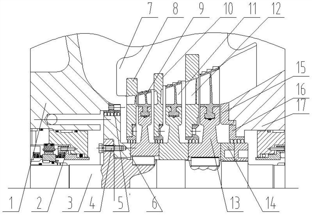
[0030] Such as figure 1 As shown, an expander axial force stabilization system, mechanical seal 2, balance air seal 5, nozzle ring seat 7 installed on the intake shell 1, balance plate bolt 4, balance plate 6, first stage turbine 9, secondary Turbine 11, last stage turbine 13, main shaft nut 14 installed on the main shaft, 5 outlet guide, final air seal 16 installed on exhaust shell 17; first stage nozzle ring 8, secondary nozzle ring 10, final stage nozzle ring 12 is installed on the nozzle ring seat 7.

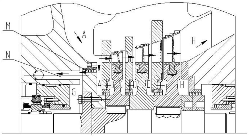
[0031] combine figure 1 see figure 2 , air inlet shell 1, nozzle ring seat 7, first stage nozzle ring 8, balance air seal 5, balance plate 6 separates chamber A, chamber internal static pressure PA; nozzle ring seat 7 first stage nozzle ring 8 first stage turbine 9 Separate chamber B, static pressure PB in the chamber; nozzle ring seat 7, primary turbine 9, secondary nozzle ring 10 separate chamber C, chamber static pressure PC; nozzle ring seat 7, secondary nozzle ring ...


PUM


Abstract

The invention discloses an organic working medium expansion machine rotor. The organic working medium expansion machine rotor has good pneumatic isentropic efficiency and reasonable axial force, can better adapt to variable working conditions, and is reasonable in structure and convenient to assemble. A chamber A is separated in an air inlet shell, and static pressure in the chamber A is PA; a chamber B is separated, and the static pressure in the chamber B is PB; a chamber C is separated, and the static pressure in the chamber C is PC; a chamber D is separated, and the static pressure in the chamber D is PD; a chamber E is separated, and the static pressure in the chamber E is PE; a chamber F is separated, and the static pressure in the chamber F is PF; a chamber H is separated, and the static pressure in the chamber H is PH; a chamber G is separated, and the static pressure in the chamber G is PG; a gap between a balance air seal and a balance disc forms an air flow channel M, an air flow channel N is formed in an air inlet shell 1, a minimum sectional area of the air flow channel M in the air flowing direction is S1, and the minimum sectional area of the air flow channel N in the air flowing direction is S2; PA> PB> PC> PD> PE>PF> PG-PH; (PA-PC)>(PC-PE)>(PE-PH); 7> (PA-PB)/ (PB-PC)> 5, 4> (PC-PD)/(PD-PE)>2; 4> (PE-PF)/ (PF-PH)> 2; 1.3H/ A> S2/ S1> H/A, PG< PH+50KPa.

Description

technical field [0001] The invention relates to the technical field of expanders, in particular to an organic working fluid expander rotor. Background technique [0002] The organic working fluid Rankine cycle system is mainly used to recycle low-grade heat energy such as low-temperature waste heat or industrial waste heat, and the organic working medium expander is the core equipment of the organic Rankine cycle system. With the advancement of energy saving and emission reduction policies, organic working fluid expanders are being used more and more in various industrial enterprises. Through efficient design, emissions can be reduced and the payback period of investment can be shortened. At the same time, changes in the load generated by the factory will cause changes in the flow rate of waste heat sources, and the operation under frequent start-stop conditions will cause large changes in the pressure at the inlet and outlet of the expander rotor and axial force, and the wo...

Claims


Application Information

Patent Timeline
Patent Type & Authority Applications(China)
IPC IPC(8): F01D1/02F01D3/02F01D9/04
Inventor 郭擎何嘉琪邓浩刁钟洋李鹏春
Owner CHONGQING JIANGJIN SHIPBUILDING IND
Why Eureka
Try Eureka