Rotary cylinder piston compressor

A compressor and rotary cylinder technology, applied in the field of compressors, can solve the problems of large piston force, many wearing parts, large friction surface, etc., and achieve the effects of improving performance, reducing leakage, and reducing relative clearance volume.

Active Publication Date: 2021-04-16
XI AN JIAOTONG UNIV
View PDF15 Cites 2 Cited by
  • Summary
  • Abstract
  • Description
  • Claims
  • Application Information

AI Technical Summary

Problems solved by technology

Traditional piston compressors need to be equipped with intake valves, exhaust valves and crank slider structural parts, with many wearing parts and complex structures; traditional rotary compressors have large friction surfaces and large piston forces

Method used


Image

  • Rotary cylinder piston compressor
  • Rotary cylinder piston compressor
  • Rotary cylinder piston compressor

Examples


Embodiment Construction

[0037] The present invention will be further described in detail below in conjunction with the accompanying drawings and embodiments. Apparently, the described embodiments are only some of the embodiments of the present invention, but not all of them. The following description of at least one embodiment is merely illustrative in nature and in no way is taken as any limitation of the invention and its application or uses. Based on the embodiments of the present invention, all other embodiments obtained by persons of ordinary skill in the art without creative efforts fall within the protection scope of the present invention.

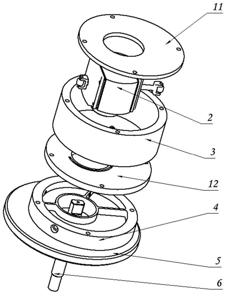
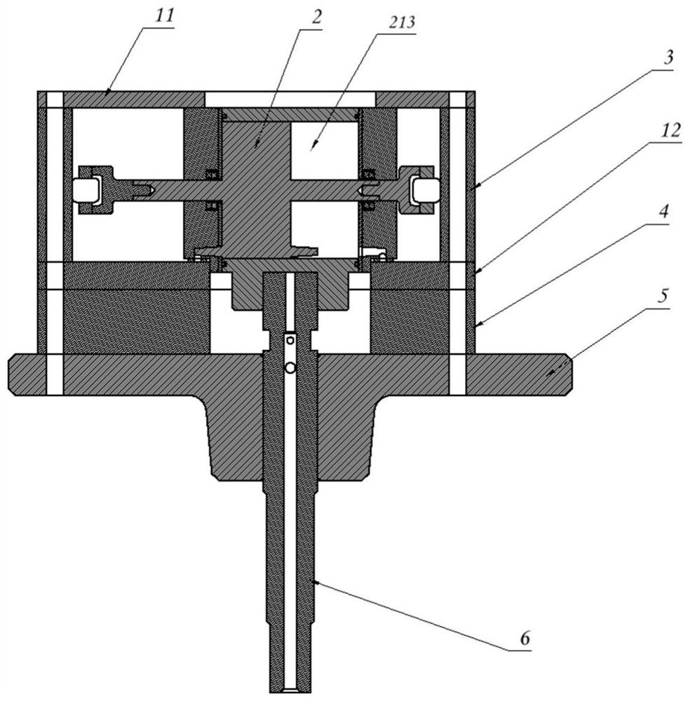
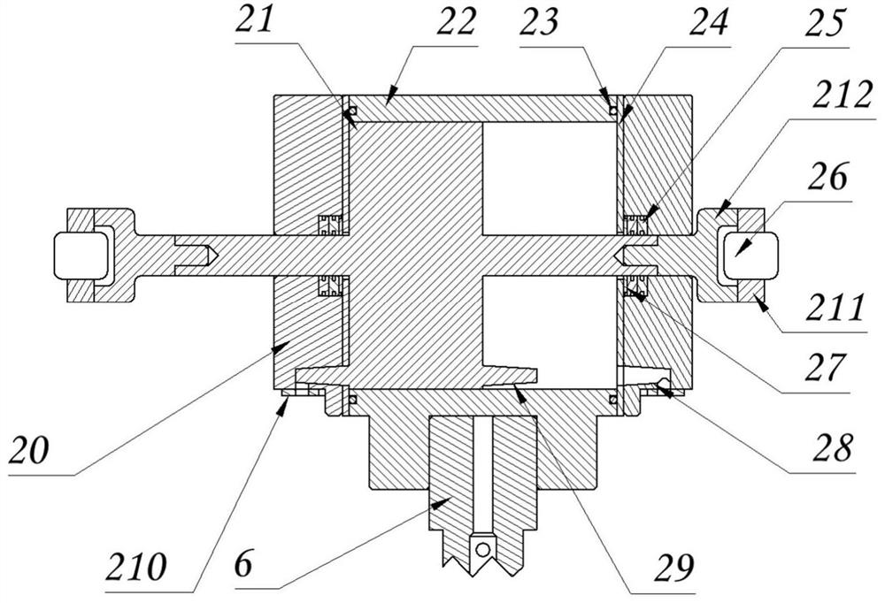
[0038] A rotary cylinder piston compressor, including an upper support plate 11, a valve plate 12, a rotating part 2, a cylinder liner 3, a valve cover 4 and a rotating shaft 6, wherein the rotating part 2 includes a piston connecting rod 21, a rotating cylinder 22, and a sealing ring 23 , Baffle 24, reciprocating sealing ring 25, needle roller bearing 26...


PUM


Abstract

The invention discloses a rotary cylinder piston compressor. The rotary cylinder piston compressor comprises a cylinder sleeve, an upper supporting plate and a valve cover, wherein the upper supporting plate and the valve cover are arranged at the two ends of the cylinder sleeve, a valve plate is arranged on the inner side of the valve cover, a cavity is defined by the valve plate, the cylinder sleeve and the upper supporting plate, a rotating component is arranged in the cavity, a rotating shaft bearing is arranged on the outer side of the valve cover, and a rotating shaft penetrates through the rotating shaft bearing to drive the rotating component to rotate; the rotating component comprises a piston connecting rod, the piston connecting rod is arranged on the air cylinder wall face in a rotary cylinder in a sleeving mode, needle bearings capable of rolling along the inner wall face of the cylinder sleeve are arranged at the two ends of the piston connecting rod, and the rotary cylinder is arranged on the rotating shaft in the sleeving mode; air cylinder end covers are symmetrically arranged on the two sides of the rotary cylinder and provided with air inlet and outlet ports. The rotary cylinder drives the piston connecting rod to rotate relative to the cylinder sleeve, and meanwhile the piston connecting rod reciprocates relative to the rotary cylinder, so that volumes of the two sides of the piston connecting rod in the rotary cylinder are changed, and air suction, compression and exhaust are achieved. According to the rotary cylinder piston compressor, quick-wear parts are reduced, the structure of the compressor is simplified, the overall stress of a piston is small, the operation is stable, and the reliability of the compressor is improved.

Description

technical field [0001] The invention belongs to the field of compressors, in particular to a rotary cylinder piston compressor. Background technique [0002] The rotary cylinder compressor is a new type of positive displacement compressor. The rotary motion of the piston relative to the cylinder liner realizes the reciprocating motion of the piston relative to the rotary cylinder; the reciprocating motion of the piston relative to the rotary cylinder realizes the periodic change of the volume of the working chamber; It is periodically communicated with the suction channel and exhaust channel of the valve plate; the above compound movement realizes the suction, compression and exhaust process of the compressor. Traditional piston compressors need to be equipped with intake valves, exhaust valves and crank slider structural parts, with many wearing parts and complex structures; traditional rotary compressors have large friction surfaces and large piston forces. [0003] With...

Claims


Application Information

Patent Timeline
Patent Type & Authority Applications(China)
IPC IPC(8): F04B37/00F04B39/00F04B39/12
Inventor 何志龙孙崇洲韦炜李丹童胡汪锋王嘉辰
Owner XI AN JIAOTONG UNIV
Why Eureka
Try Eureka