Pipe hot air heating box and pipe hot air heating device thereof

A hot air heating and practical technology, which is applied in the field of hot air heating boxes for pipes, can solve the problems of troublesome replacement operation, unreasonable structure, and small heating port area in the air inlet area C, so as to achieve a good utilization rate of heat energy and is suitable for industrial production , the effect of convenient technology

Active Publication Date: 2017-11-10
ZHANGJIAGANG XIEXIN MACHINERY
View PDF8 Cites 0 Cited by
  • Summary
  • Abstract
  • Description
  • Claims
  • Application Information

AI Technical Summary

Problems solved by technology

However, the structure of this hot air recirculation heating box is not suitable for industrial production, and it has at least the following disadvantages: 1. The hot air recirculation heating box can only be suitable for heating pipes of one specification. The reflow heating box, and the replacement operation is also troublesome; 2. The production and processing of the hot air reflow heating box is difficult and the structure is unreasonable. The inside of the hot air reflow heating box has a windshield, an air inlet The windshield, windshield and heat preservation cover are all arranged in the annular cavity, so if the heating box is a whole, then it is impossible to process and fix the windshield, wind inlet hood, and heat preservation cover in the annular cavity, that is to say, one The structure is not practical at all; and it is mentioned in the manual that the hot air return heating box is a split structure, and it is tied into a whole by chains. However, this structure is not reasonable. First, the hot air return heating box is split Therefore, the windshield, the wind inlet hood and the heat preservation cover are divided into two halves. Although the three can be fixed in the annular cavity, when the two halves are fastened and fastened, it is still impossible. To ensure the accurate fit and docking of the two halves of the windshield, the air inlet hood and the insulation cover itself, it is impossible to guarantee the absolute separation between the air inlet area C and the return area F, and there will be a hot air passage between the two, and The pressure in the air inlet area C is high when the air enters, and the pressure in the return area F is low because the air is drawn away. In this way, once there is a circulation channel between the two, the hot air will directly leak from the air intake area C to the return area F. The area of ​​the heating opening in the air inlet area C is small, and after being blocked by the windshield ring 123, the flow route of the hot air from the air inlet area C into the heating area D and then into the heat preservation area E and then into the return area F is originally large in wind resistance. As a result, the above-mentioned phenomenon that the hot air inlet area C directly leaks into the return area F is more obvious, so that the effect of hot air heating is not obvious, and the effect of heat preservation is not obvious. Even, for this split structure, if the processing accuracy And when the assembly accuracy is poor, a large amount of hot air will leak directly and the pipe will not be heated according to the flow route

Method used


Image

  • Pipe hot air heating box and pipe hot air heating device thereof
  • Pipe hot air heating box and pipe hot air heating device thereof
  • Pipe hot air heating box and pipe hot air heating device thereof

Examples


Embodiment 1

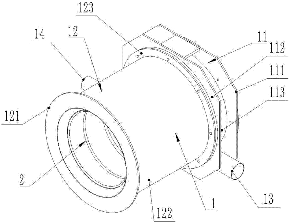
[0031] like Figure 1 to Figure 7 As shown, a hot air heating box for pipes includes an inner cylinder 2 and an outer cylinder 1, and the outer cylinder 1 includes a concentrically connected air inlet cylinder section 11 and a return air cylinder section 12, and the air inlet cylinder section 11 is provided with Air inlet pipe mouth 13, described air return tube section 12 is provided with return air pipe mouth 14, as figure 1 and image 3 , Figure 4 As shown, the air return cylinder section 12 includes an inner air return cylinder 124 and an outer air return cylinder 122 fixed concentrically, and a heat insulating material is arranged between the inner air return cylinder 124 and the outer return air cylinder 122 or vacuum environment. The setting of the vacuum environment is relatively difficult, but this method can also be used, that is, a negative pressure tuyere can be set on the external return air cylinder 122 to suck air to form a vacuum environment. Generally, hea...

Embodiment 2

[0038] This embodiment discloses a hot-air heating device for pipes. The hot-air heating device uses the above-mentioned hot-air heating box for pipes. The air duct opening 14 is connected to the air return port of the blower fan 4 through the air return duct 7, and the air inlet duct 6 is provided with a heater 5 which heats the air in the air inlet duct 6. Generally, the heater 5 adopts electric heating. device 5.

[0039] The working principle of this embodiment is: the pipe moves axially through the through opening, and the fan 4 sends the heated hot air into the air inlet nozzle 13, and then enters the heating chamber. Due to the existence of the annular shrinking cone surface 213, the hot air Gather, the temperature increases, and then form a hot air knife through the heating tuyeres 216, so that the surface of the pipe will be heated, and the hot air will flow into the heat preservation chamber along the gap between the pipe and the through hole 15, and then the pipe wi...


PUM


Abstract

The invention discloses a pipe hot air heating box which comprises an inner barrel and an outer barrel. The outer barrel comprises an air inlet barrel section and an air return barrel section. The inner barrel comprises a heating barrel section and a heat preservation barrel section. A through hole is formed in the heating barrel section. An annular contracted conical surface is arranged on the heating barrel section. A heating cavity is formed between the outer side face of the contracted conical surface and the air inlet barrel section. A heating air port is annularly formed in the inner side wall of the heating cavity. A heat preservation cavity is formed between an inner hole of the heat preservation barrel section and a pipe penetrating through the through hole. An air return cavity is formed between the heat preservation barrel section and the air return barrel section. The downstream end of the heat preservation cavity communicates with the air return cavity. The air return cavity communicates with an air return pipe opening. The pipe hot air heating box is reasonable in structure, quite convenient to assemble and disassemble, reliable in heating effect, higher in heat utilization rate and smaller in heat loss. In addition, the invention further discloses a hot air heating device using the hot air heating box, and the hot air heating device has the same effects as the pipe hot air heating box.

Description

technical field [0001] The invention relates to a hot air heating box for pipes, which is used for heating the surface of pipe materials, and also relates to a hot air heating device for pipes using the hot air heating box for pipes. Background technique [0002] In the current production process of composite pipes, in order to improve the mechanical properties of the pipes, it is necessary to heat the surface of the pipes and then wrap the reinforcing tape. In order to make the surface of the pipes reach the temperature required for bonding, it is necessary to use a heating device to heat the pipes. However, at present There are two general methods, one is to use a ceramic heating device to heat, and the other is to use hot air to heat, but the ceramic is easy to burn out after long-term use, and it is more complicated to disassemble and replace. And another kind of hot air heating adopts hot air heating, so as long as the continuous blowing of hot air can ensure heating, i...

Claims


Application Information

Patent Timeline
Patent Type & Authority Applications(China)
IPC IPC(8): B29C65/48
CPCB29C65/48B29C66/50B29C66/87
Inventor 陆宇航
Owner ZHANGJIAGANG XIEXIN MACHINERY
Why Eureka
Try Eureka