Support mechanism and automatic lifting device with the mechanism

A support mechanism and automatic lifting technology, applied in the field of support mechanism, can solve the problems of complex structure, difficult installation, no buffer and vibration reduction of the support mechanism, and achieve the effects of avoiding hard mechanical contact, reducing production cost and ensuring cleanliness

Inactive Publication Date: 2011-12-14
DONGGUAN ANWELL DIGITAL MASCH CO LTD
View PDF0 Cites 0 Cited by
  • Summary
  • Abstract
  • Description
  • Claims
  • Application Information

AI Technical Summary

Problems solved by technology

[0003] The existing support mechanism for supporting and lifting the substrate does not have the function of buffering and vibration reduction. The support mechanism directly touches the substrate. During the process of supporting and lifting the substrate, hard mechanical contact is likely to cause it to be supported and / or The lifted substrate is damaged, which reduces the yield of products; another support mechanism has the function of air pressure damping or hydraulic damping. In the plating equipment, this inevitably brings pollution from the equipment itself to the vacuum environment, reduces the cleanliness of the vacuum equipment, and affects the evaporation effect; at the same time, the introduction of vacuum equipment such as air cylinders or hydraulic cylinders makes the structure of the support mechanism complex, Difficult to install and high manufacturing cost, while the support mechanism is located in the vacuum equipment and difficult to maintain

Method used


Image

  • Support mechanism and automatic lifting device with the mechanism
  • Support mechanism and automatic lifting device with the mechanism
  • Support mechanism and automatic lifting device with the mechanism

Examples


Embodiment Construction

[0021] Embodiments of the present invention will now be described with reference to the drawings, in which like reference numerals represent like elements.

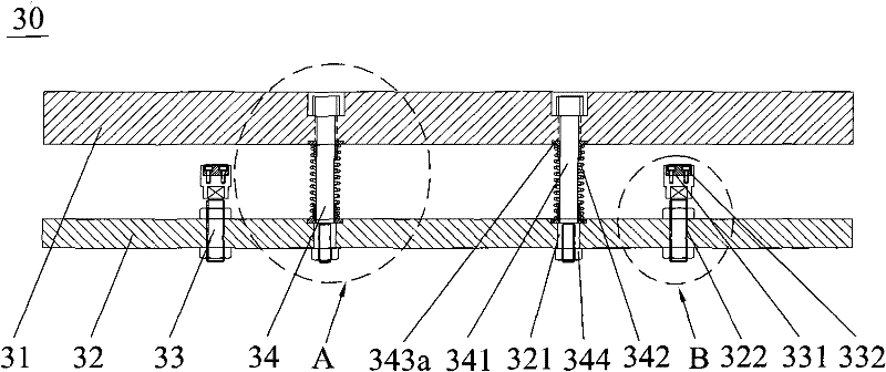
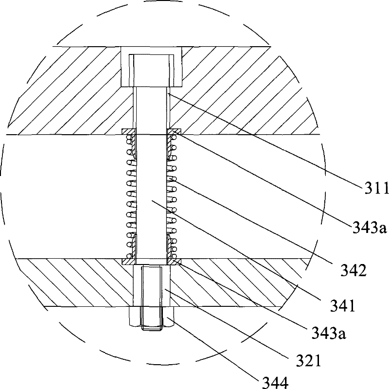
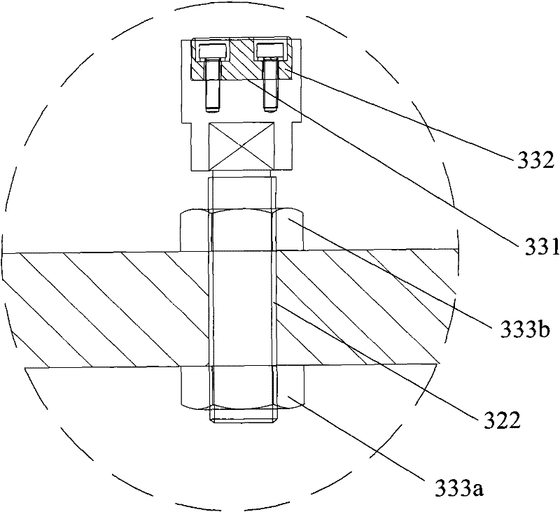
[0022] Such as Figure 1-Figure 3As shown, the supporting mechanism 30 of the present invention includes a mounting plate 32, a loading plate 31, a connecting piece 34 and a limiting piece 33, and the connecting piece 34 and the limiting piece 33 are connected between the installing plate 32 and the loading plate 31 in parallel with each other. Wherein, the connector 34 includes a connecting column 341 and an elastic element 342, the upper end of the connecting column 341 is movably connected with the bearing plate 31, the lower end of the connecting column 341 is movably connected with the mounting plate 32, and the elastic element 342 is sleeved on the connecting column in a compressed form. 341, and the upper end of the elastic element 342 is in conflict with the bearing plate 31, the lower end of the elastic element 3...


PUM


Abstract

The invention discloses a supporting mechanism, which comprises a mounting plate, a bearing plate, a connecting piece and a limiting piece, the connecting piece and the limiting piece are connected between the installing plate and the bearing plate in parallel with each other, and the connecting piece includes a connecting column and an elastic The upper end of the connecting column is movably connected with the bearing plate, the lower end of the connecting column is movably connected with the mounting plate, the elastic element is sleeved outside the connecting column in a compressed form, and the upper end of the elastic element is in conflict with the bearing plate, and the lower end of the elastic element is in contact with the loading plate. The mounting plate conflicts, the lower end of the spacer is connected to the mounting plate, the upper end of the spacer extends along the direction of the load plate, and the upper end of the spacer is also provided with a soft cushion; The hard mechanical contact between the bearing plate and the loaded object prevents the loaded object from being damaged, and the structure is simple and easy to maintain. In addition, the invention also discloses an automatic lifting device with the support mechanism of the invention.

Description

technical field [0001] The invention relates to a support mechanism, in particular to a support mechanism with a buffer function for supporting flat-plate devices and an automatic lifting device with the support mechanism. Background technique [0002] Flat panel display (FPD, Flat Panel Display) will become the mainstream product in the display due to its advantages of thinness, lightness, low power consumption, and low radiation. The flat panel display mainly includes liquid crystal display LCD (Liquid Crystal Display), plasma display PDP (Plasma Display Panel ), organic electroluminescent display OLED (Organic Light Emitting Display) and surface conduction electron emission display SED (Surface-conduction Electron-emitter Display) and other major technology types; the production of various types of display devices requires the use of glass as substrates Carry out vacuum coating, and deposit multi-layer thin films successively on the glass substrate. Taking OLED as an exam...

Claims


Application Information

Patent Timeline
Patent Type & Authority Patents(China)
IPC IPC(8): C23C14/24
Inventor 杨明生刘惠森范继良张永红王曼媛王勇
Owner DONGGUAN ANWELL DIGITAL MASCH CO LTD
Why Eureka
Try Eureka