Eureka AIR delivers breakthrough ideas for toughest innovation challenges, trusted by R&D personnel around the world.

Control circuit and method for air conditioner

A technology for controlling circuits and air conditioners, applied in heating and ventilation control systems, heating methods, space heating and ventilation, etc., can solve problems affecting the normal cooling function of the whole machine, compressor reliability, lack of intelligent control modes, etc. It achieves the effects of avoiding abnormal overload protection of the compressor, avoiding incomplete defrosting of the evaporator, and solving limited space

Active Publication Date: 2021-04-16
GREE ELECTRIC APPLIANCES INC
View PDF9 Cites 0 Cited by
  • Summary
  • Abstract
  • Description
  • Claims
  • Application Information

AI Technical Summary

Problems solved by technology

[0002]The existing window air conditioner controlled by mechanical master switch adopts knob type thermostat as the temperature control switch, which has intuitive control interface, simple operation and convenience advantages, but because the master switch as the main control unit is a mechanical switch, it only has simple cooling and air supply control functions, and lacks an intelligent control mode. In practical applications, it takes 3 minutes between the shutdown and restart of the compressor. Delay is the basic requirement for the compressor control of the whole machine. The purpose is to avoid the compressor from stopping and starting in a short time, causing the system pressure to be too high, causing the compressor overload protection failure; the ordinary master-controlled window machine cannot realize this function. , when used in some schools or public places, students will frequently start and stop the operation of the compressor, resulting in frequent compressor overload protection, affecting the normal cooling function of the whole machine and the reliability of the compressor

Method used


Image

  • Control circuit and method for air conditioner
  • Control circuit and method for air conditioner
  • Control circuit and method for air conditioner

Examples


Embodiment Construction

[0042] In order to make the purpose, technical solutions and advantages of the embodiments of the present invention clearer, the technical solutions in the embodiments of the present invention will be clearly and completely described below in conjunction with the drawings in the embodiments of the present invention. Obviously, the described embodiments It is a part of embodiments of the present invention, but not all embodiments. Based on the embodiments of the present invention, all other embodiments obtained by persons of ordinary skill in the art without creative efforts fall within the protection scope of the present invention.

[0043] Terms used in the embodiments of the present invention are only for the purpose of describing specific embodiments, and are not intended to limit the present invention. The singular forms "a", "said" and "the" used in the embodiments of the present invention and the appended claims are also intended to include plural forms, unless the conte...


PUM


Abstract

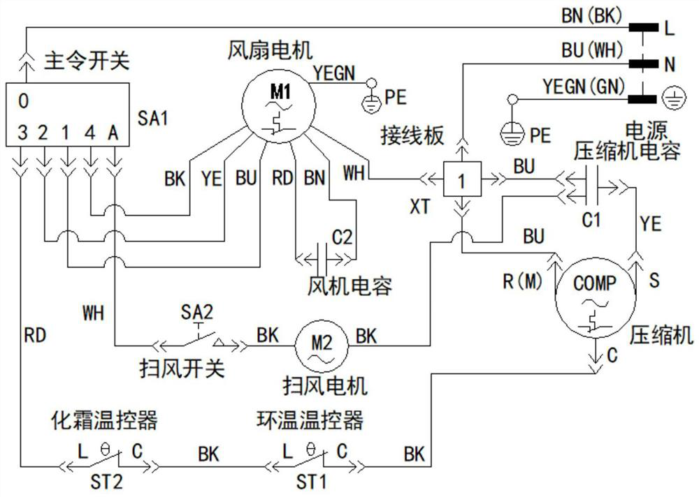
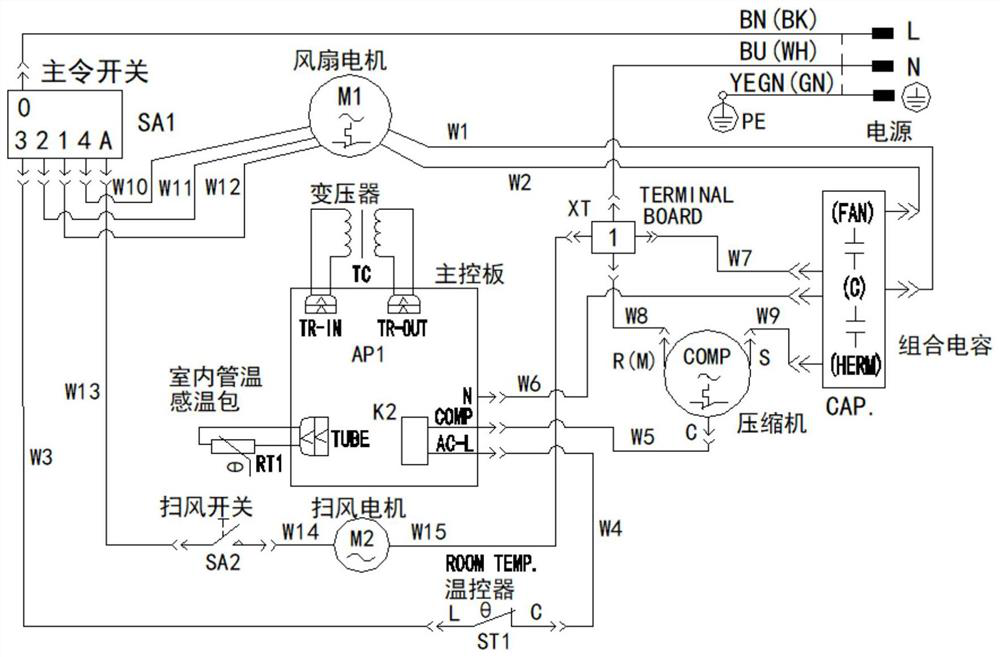
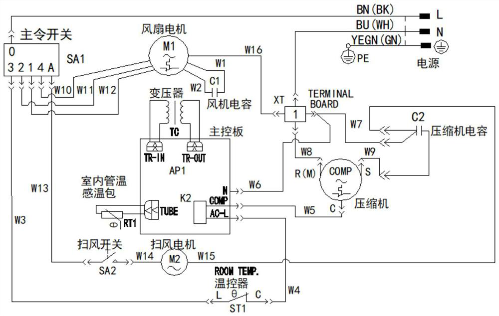
The embodiment of the invention relates to the technical field of air conditioners, in particular to a control circuit and method for an air conditioner. The control circuit for the air conditioner comprises a master switch and a compressor control circuit, the master switch comprises a power supply input end and a compressor power supply end which can be switched on or switched off, the compressor control circuit comprises a CPU microcomputer circuit, a relay and a compressor, the relay comprises a first contact and a second contact which can be connected or disconnected, the first contact is connected with the power supply end of the compressor, the second contact is connected with the common end of the compressor, and when the first contact is electrified and the CPU microcomputer circuit delays for set time, the first contact and the second contact of the relay are controlled to be in conduction connection. According to the control circuit for the air conditioner in the embodiment, the compressor delay control function can be achieved, and frequent starting and stopping of the compressor are avoided.

Description

technical field [0001] The invention relates to the technical field of air conditioners, in particular to an air conditioner control circuit and a control method thereof. Background technique [0002] The existing window-type air conditioners controlled by mechanical master switches use knob-type thermostats as temperature control switches, which have the advantages of intuitive control interface, simple operation, and convenience. However, since the master switch as the main control unit is mechanical Type switch, only simple cooling and air supply control functions, lack of intelligent control mode, in practical applications, a 3-minute delay between compressor shutdown and restart is the basic requirement for the compressor control of the whole machine, the purpose is Avoid the short-term stop and start of the compressor, resulting in excessive system pressure, causing compressor overload protection failures; ordinary master-controlled window machines cannot achieve this ...

Claims


Application Information

Patent Timeline
Patent Type & Authority Applications(China)
IPC IPC(8): F24F11/88F24F11/63F24F11/41F24F11/65F24F11/64F24F11/61
Inventor 郑文力王后军吴晓康姚新祥李和坤黄冠豪
Owner GREE ELECTRIC APPLIANCES INC
Why Eureka
Eureka Blog
Learn More