Luminous target object video agglomerate fog visibility monitoring method

A target and visibility technology, applied in complex mathematical operations, instruments, character and pattern recognition, etc., can solve the problems of unstable observation value, difficult all-day application, harsh light source conditions, etc.

Active Publication Date: 2021-04-16
日照市气象局
View PDF10 Cites 0 Cited by
  • Summary
  • Abstract
  • Description
  • Claims
  • Application Information

AI Technical Summary

Problems solved by technology

Some studies have been transformed into experimental products, such as the monitoring of visibility based on the digital camera visibility system and its comparative experiments. Two groups of target black bodies and target light source units with different distances on a straight line are photographed and the visibility is calculated based on the relationship between visibility and extinction coefficient. , the light source conditions are very harsh, and the observation value is not stable enough in the early morning and evening, so it is difficult to apply all day

Method used


Image

  • Luminous target object video agglomerate fog visibility monitoring method
  • Luminous target object video agglomerate fog visibility monitoring method
  • Luminous target object video agglomerate fog visibility monitoring method

Examples


Embodiment 1

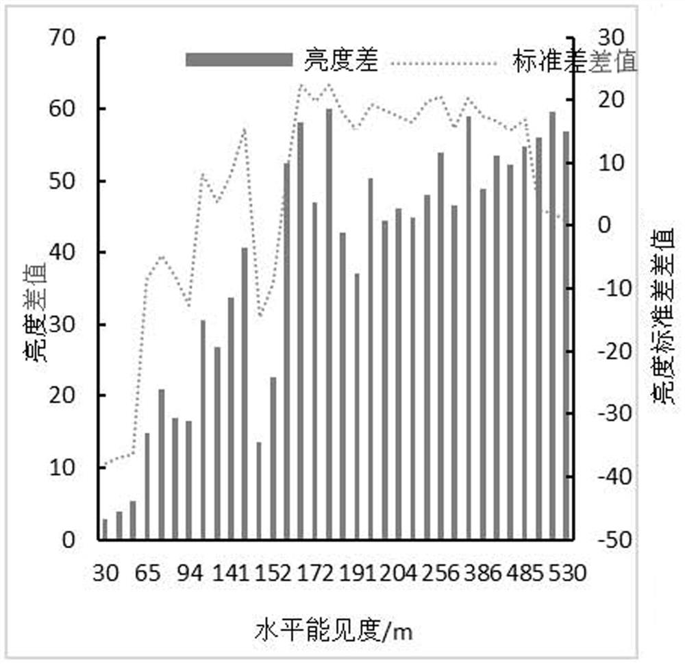
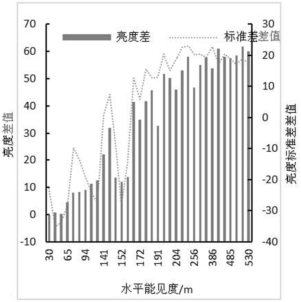
[0074] A method for monitoring the visibility of luminous target objects in video group fog, comprising the following steps: S1, select a section of road where group fog occurs frequently, set a plurality of cameras, and set a constant light that is always bright at a distance of 50m, 100m, and 200m from a single camera, respectively, The camera acquires the corresponding video images of the three constant illuminants in real time;

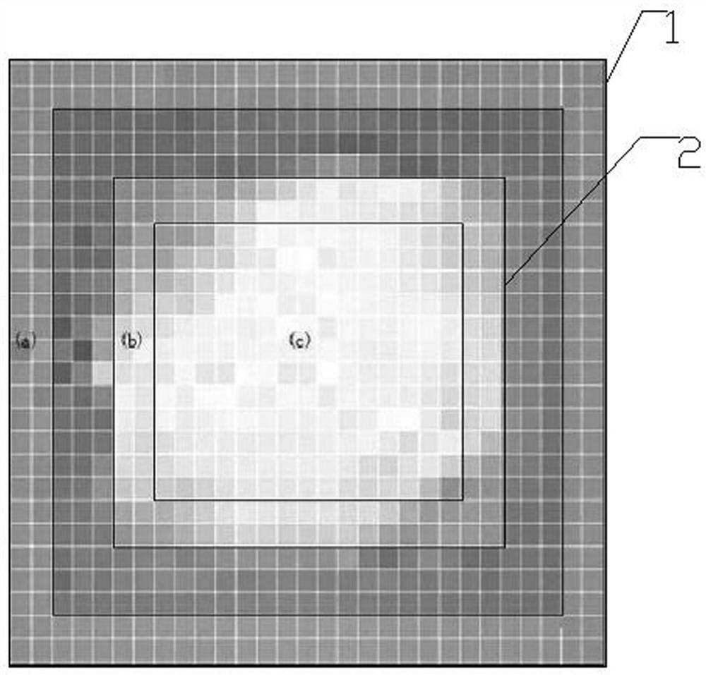
[0075] S2, every fixed time, take screenshots of the video images of the constant illuminants shot at a distance of 50m, 100m, and 200m from the camera, and capture the screenshots of the rectangular frame area centered by the constant illuminants in the video screenshots as light domain feature pictures;

[0076] S3, analyze the light domain feature picture, and determine three characteristic rectangular ring areas from the center point of the rectangular frame area to the surroundings, namely the central area c of the light domain, the edge area ...

Embodiment 2

[0087] The difference between this embodiment and Embodiment 1 is that the height of the constant illuminant from the ground is 3-5 m, and the height of the camera is higher than that of the constant illuminant. The camera and the constant illuminant are arranged on both sides of the road or on the same side.

Embodiment 3

[0089] The difference between this embodiment and embodiment 1 is that in step 2 every 3-10 seconds intercept Figure 1 times, the interval between capturing video images is short, and the monitoring accuracy is improved.


PUM


Abstract

The invention discloses a luminous target object video agglomerate fog visibility monitoring method, which comprises the following steps of: setting a plurality of cameras, respectively setting normally-on constant luminous bodies at the positions which are 50m, 100m and 200m away from a single camera, and capturing a rectangular square frame area screenshot in the middle of the constant luminous bodies in a video screenshot as an optical domain characteristic picture. Three characteristic rectangular ring areas are determined from the center point of the rectangular square frame area to the periphery, and according to the brightness difference, the standard deviation, the ring mark difference value, the heart ring difference value and the horizontal visibility linear regression model of the constant illuminants, the average horizontal visibility between the camera and the constant illuminants at the positions of 50 m, 100 m and 200 m is obtained. The luminous target object video agglomerate fog visibility monitoring method can continuously monitor the average visibility in real time for 24 hours, can effectively monitor the agglomerate fog weather, can improve the timeliness and accuracy of monitoring, can assist in quickly determining the agglomerate fog generation section, and can reduce traffic accidents caused by highway agglomerate fog.

Description

technical field [0001] The invention relates to the technical field of meteorological monitoring, in particular to a method for monitoring the visibility of a luminous target object through video cloud fog. Background technique [0002] Fog is usually generated in small and medium-scale circulation systems, and is distributed in clusters. The coverage of highway fog is relatively small, often less than 5 kilometers. The horizontal visibility in the fog is very low, and the visibility is less than 200 meters. Expressway fog has been recognized as a "mobile killer", often causing major traffic accidents, and the accident fatality rate is higher than other traffic accidents. Compared with other fogs, cluster fog has the characteristics of locality, small range, suddenness, and easy flow, which greatly affects the timeliness and accuracy of monitoring. [0003] Domestic research started late and developed rapidly, which can be roughly classified into three types. The first cat...

Claims


Application Information

Patent Timeline
Patent Type & Authority Applications(China)
IPC IPC(8): G06K9/00G06K9/46G06K9/52G06F17/18
Inventor 卢振礼李玉华杨成芳崔广署安源路伟
Owner 日照市气象局
Why Eureka
Try Eureka