Line alignment method, device and equipment for Ethernet physical coding sublayer PCS
A technology of physical coding sublayer and Ethernet, which is applied in the line pair alignment field of Ethernet physical coding sublayer PCS, can solve the problems of increasing hardware overhead and long processing time, and achieve the goal of reducing overhead and delay detection time Effect
- Summary
- Abstract
- Description
- Claims
- Application Information
AI Technical Summary
Problems solved by technology
Method used
Image

Examples
Embodiment 1
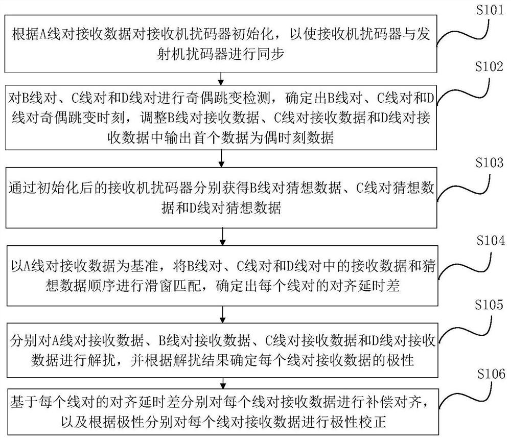
[0037] Fig. 1 (a) is the flow chart of the wire pair alignment method of the Ethernet physical coding sublayer PCS provided by Embodiment 1 of the present invention, and this embodiment is applicable to the situation of aligning the wire pairs in the PCS layer in the receiver , the method can be executed by the line pair alignment device of the Ethernet physical coding sublayer PCS in the embodiment of the present invention, and the device can be implemented by software and / or hardware. As shown in Figure 1(a), the method specifically includes the following operations:
[0038] Step S101, initialize the receiver scrambler according to the received data on the A line, so that the receiver scrambler is synchronized with the transmitter scrambler.
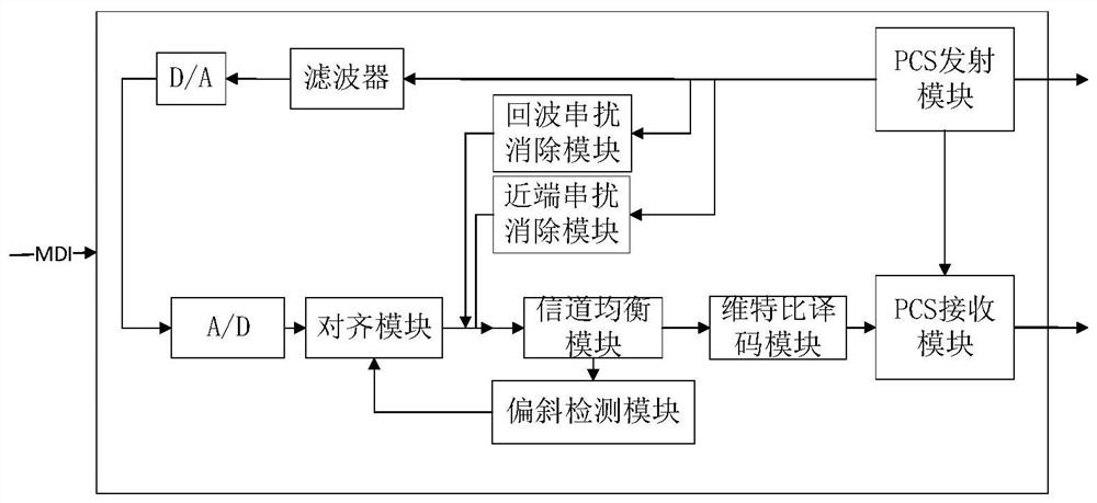
[0039] Specifically, as shown in Figure 1(b), it is a schematic diagram of the transceiver link of the transmitter and the receiver provided by the embodiment of the present invention. A PCS alignment module is added to the transmitte...
Embodiment 2
[0068] figure 2 It is a flow chart of the line pair alignment method of the Ethernet physical coding sublayer PCS provided by Embodiment 2 of the present invention. This embodiment is based on the above-mentioned embodiment, and each line is separately aligned based on the alignment delay difference of each line pair. After the compensation alignment is performed on the received data, detection of compensation alignment and polarity correction results is also included. Correspondingly, the method in this embodiment specifically includes the following operations:
[0069] Step S201, initialize the receiver scrambler according to the received data on the A line, so that the receiver scrambler and the transmitter scrambler are synchronized.
[0070] Optionally, the receiver scrambler is initialized according to the received data of the A-line pair, so that the receiver scrambler and the transmitter scrambler are synchronized, which may include: acquiring the intermediate bit at ...
Embodiment 3
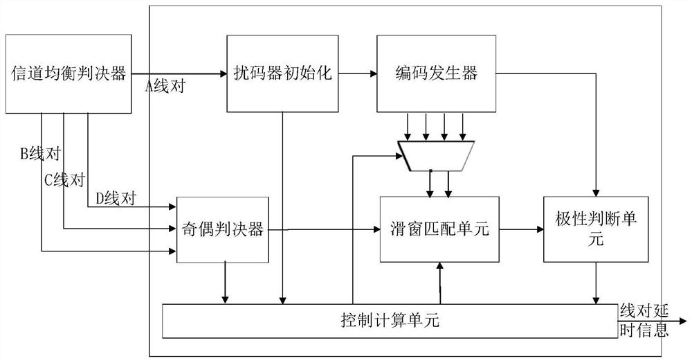
[0083] image 3 An Ethernet physical coding sublayer PCS line pair alignment device provided for an embodiment of the present invention, the device includes: a receiver scrambler initialization module 310, a parity jump detection module 320, a line pair guess data generation module 330, Sliding window matching module 340 polarity determination module 350 and alignment and polarity correction module 360 .
[0084] Wherein, the receiver scrambler initialization module 310 is used to initialize the receiver scrambler according to the received data of the A line, so that the receiver scrambler and the transmitter scrambler are synchronized;
[0085] The parity jump detection module 320 is used to perform parity jump detection on the B line pair, the C line pair, and the D line pair, determine the parity jump time of the B line pair, the C line pair, and the D line pair, and adjust the reception of the B line pair. Data, C line pair receiving data and D line pair receiving data ...
PUM
 Abstract
Description
Claims
Application Information
 - R&D
- Intellectual Property
- Life Sciences
- Materials
- Tech Scout
- Unparalleled Data Quality
- Higher Quality Content
- 60% Fewer Hallucinations
Browse by: Latest US Patents, China's latest patents, Technical Efficacy Thesaurus, Application Domain, Technology Topic, Popular Technical Reports.
© 2025 PatSnap. All rights reserved.Legal|Privacy policy|Modern Slavery Act Transparency Statement|Sitemap|About US| Contact US: help@patsnap.com