Ecological agriculture water-saving irrigation system
An irrigation system and ecological agriculture technology, applied in the field of ecological agriculture water-saving irrigation system, can solve problems such as inability to realize precise quantitative control and no practical application value
- Summary
- Abstract
- Description
- Claims
- Application Information
AI Technical Summary
Problems solved by technology
Method used
Image
Examples
Embodiment 1
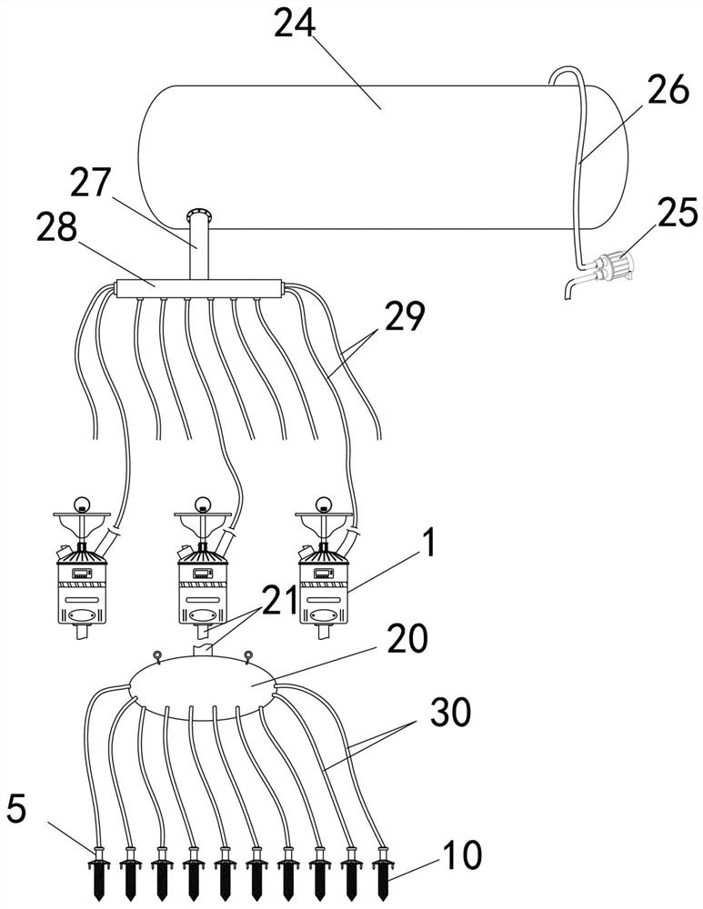
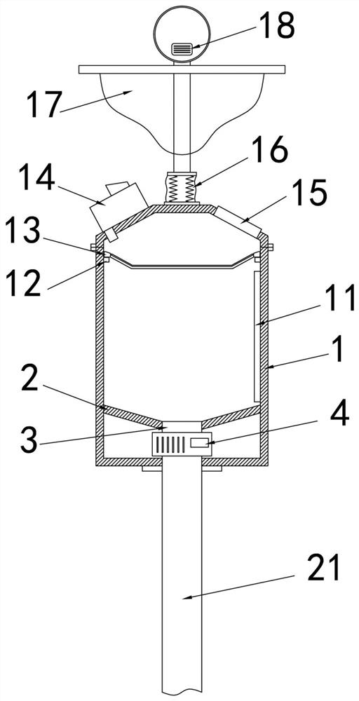
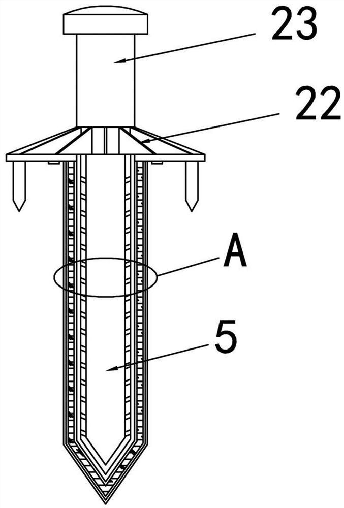
[0030] Embodiment 1: as Figure 1-3 As shown, the ecological agricultural water-saving irrigation system proposed by the present invention includes a water supply system, a water diversion device, an intermediate water supply unit and a drip irrigation intubation pipe, and the drainage main pipe 27 of the output part of the water supply system is divided into a plurality of drainage branch pipes 29 by the water diversion device. , each drainage branch pipe 29 communicates with the corresponding intermediate water supply unit respectively, and the intermediate water supply unit includes a water tank part and a buffer water bag part, and the two parts are respectively fixed on the corresponding brackets and communicated with each other through the transition pipe 21 as a whole (control water tank The height of the part can change the water inlet speed and water inlet volume of the intermediate water supply unit, and the drip irrigation speed and drip irrigation water volume can b...
Embodiment 2
[0040] Example 2: After the water tank 1 of the intermediate water supply unit in the scheme of Example 1 is filled with water, in order to keep it flowing downward smoothly, the upper end needs to have a vent hole, but the existence of the vent hole leads to the water tank 1 of the intermediate water supply unit The water level may overflow, that is, the continuous water supply of the water supply system will cause a steady stream of water to overflow from the vent hole. In view of this problem, this embodiment improves on the basis of the water tank of Embodiment 1. The top of the water tank 1 is set as a conical top 31, and the inner side is matched with a conical floating body 33 or a floating ball. When the water level rises to a certain height, The conical floating body 33 or the floating ball float upwards to block the air inlet 32 at the upper end. In order to ensure that the conical floating body 33 or the floating ball moves upwards smoothly, a guide rod 35 is fixe...
Embodiment 3
[0041] Example 3: After the water tank 1 of the intermediate water supply unit in the scheme of Example 1 is filled with water, in order to keep it flowing downward smoothly, the upper end needs to have air holes, but the existence of the air holes leads to the water tank 1 of the intermediate water supply unit The water level may overflow. The way to solve this technical problem is different from embodiment 2 in this implementation. In this embodiment, a liquid level sensor needs to be installed in the water tank, and a water inlet solenoid valve is installed on the water inlet or the water inlet pipe of the water tank. And it is controlled by the controller to open and close. When the water level in the water tank is high, it will automatically control the water supply to cut off. In addition to realizing the corresponding functions as in Embodiment 2, this function can also control the water supply volume, aiming at the overall water supply control of some intermediate water...
PUM
 Abstract
Description
Claims
Application Information
 - R&D
- Intellectual Property
- Life Sciences
- Materials
- Tech Scout
- Unparalleled Data Quality
- Higher Quality Content
- 60% Fewer Hallucinations
Browse by: Latest US Patents, China's latest patents, Technical Efficacy Thesaurus, Application Domain, Technology Topic, Popular Technical Reports.
© 2025 PatSnap. All rights reserved.Legal|Privacy policy|Modern Slavery Act Transparency Statement|Sitemap|About US| Contact US: help@patsnap.com


