Hydraulic control square block stamping device
A stamping device and square block technology, applied in the hydraulic field, can solve problems such as square block cracks and square block deformation
- Summary
- Abstract
- Description
- Claims
- Application Information
AI Technical Summary
Problems solved by technology
Method used
Image

Examples
Embodiment Construction
[0022] The following will clearly and completely describe the technical solutions in the embodiments of the present invention with reference to the accompanying drawings in the embodiments of the present invention. Obviously, the described embodiments are only some, not all, embodiments of the present invention. Based on the embodiments of the present invention, all other embodiments obtained by persons of ordinary skill in the art without making creative efforts belong to the protection scope of the present invention.
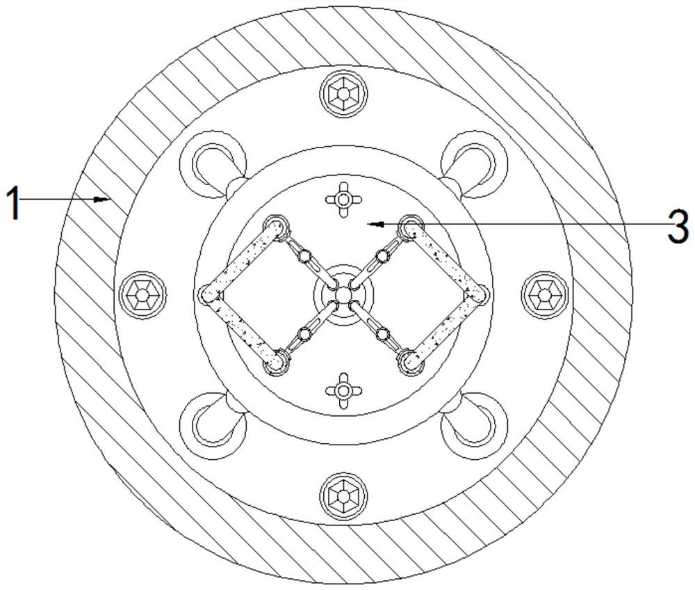
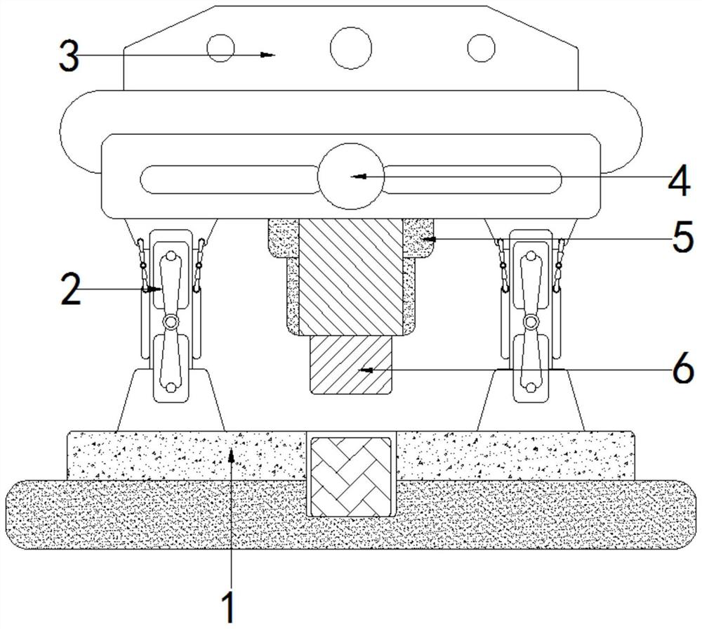
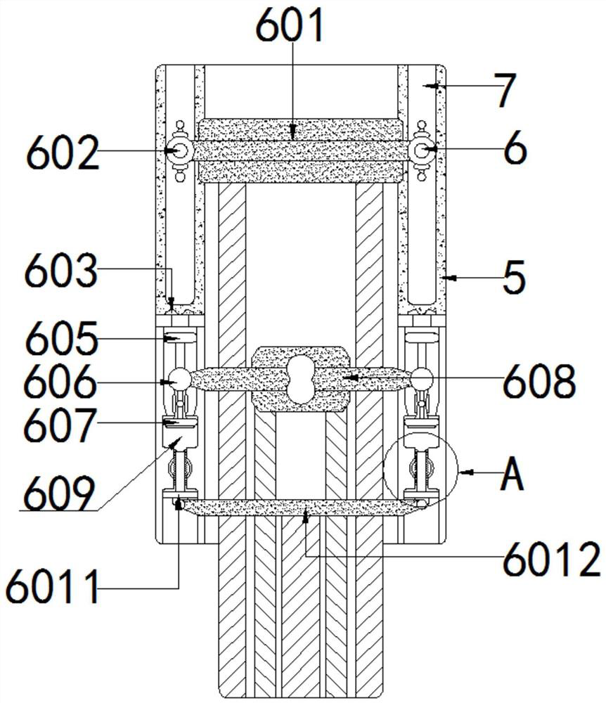
[0023] see Figure 1-7 , a hydraulically controlled square block punching device, comprising a base 1, a bracket 2, a top seat 3, a convex seat cover 5 and a stamping assembly 6, the top of the base 1 is fixedly installed with the bottom end of the bracket 2, and the top of the bracket 2 is connected to the top seat The bottom end of 3 is fixedly installed, the inner wall of top seat 3 is fixedly installed with hydraulic tank 4, the bottom end of top seat 3 an...
PUM
 Abstract
Description
Claims
Application Information
 - Generate Ideas
- Intellectual Property
- Life Sciences
- Materials
- Tech Scout
- Unparalleled Data Quality
- Higher Quality Content
- 60% Fewer Hallucinations
Browse by: Latest US Patents, China's latest patents, Technical Efficacy Thesaurus, Application Domain, Technology Topic, Popular Technical Reports.
© 2025 PatSnap. All rights reserved.Legal|Privacy policy|Modern Slavery Act Transparency Statement|Sitemap|About US| Contact US: help@patsnap.com