
Deburring device for circuit breaker machining

A circuit breaker and burr technology, which is applied to metal processing equipment, metal processing machinery parts, manufacturing tools, etc., can solve problems such as low automation, low work efficiency, and fuzzy division of high and low voltage boundaries

Inactive Publication Date: 2021-04-20
王纪华
View PDF0 Cites 0 Cited by
  • Summary
  • Abstract
  • Description
  • Claims
  • Application Information

AI Technical Summary

Problems solved by technology

[0002] A circuit breaker refers to a switching device that can close, carry and break current under normal circuit conditions and can close, carry and break current under abnormal circuit conditions within a specified time. Circuit breakers are divided into For high-voltage circuit breakers and low-voltage circuit breakers, the division of high and low voltage boundaries is relatively vague. Generally, those above 3kV are called high-voltage electrical appliances. Circuit breakers can be used to distribute electric energy, start asynchronous motors infrequently, and protect power lines and motors. When they It can automatically cut off the circuit in the event of serious overload, short circuit and undervoltage faults. Its function is equivalent to the combination of fuse switch and overheating and underheating relay, etc., and generally does not need to change parts after breaking the fault current. At present, it has It has been widely used. During the processing and use of circuit breakers, it is necessary to clean the burrs on the circuit breaker. At present, in the cleaning process, workers usually need to use tools to clean the circuit breaker burrs, which is prone to danger during the cleaning process. , increasing the burden on the staff, the degree of automation is low, resulting in low work efficiency and poor practicability

Method used


Image

  • Deburring device for circuit breaker machining
  • Deburring device for circuit breaker machining
  • Deburring device for circuit breaker machining

Examples


Embodiment Construction

[0020] The specific embodiments of the present invention will be described in further detail below with reference to the accompanying drawings and examples. The following examples are used to illustrate the present invention, but are not intended to limit the scope of the present invention.

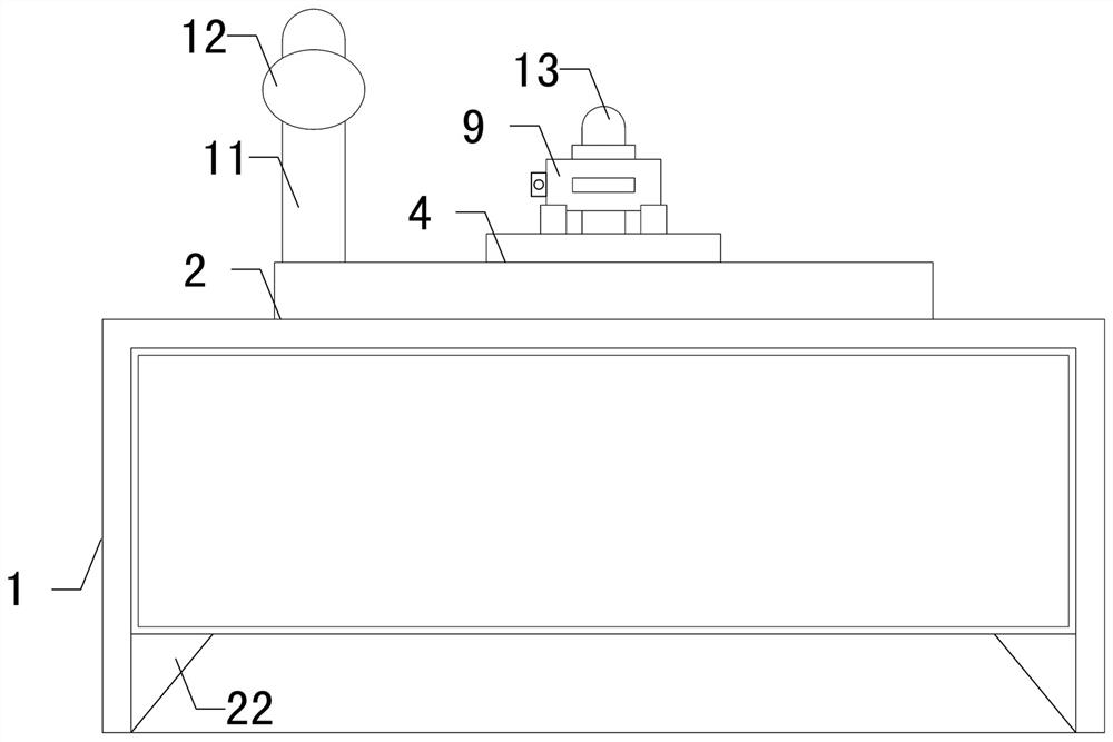
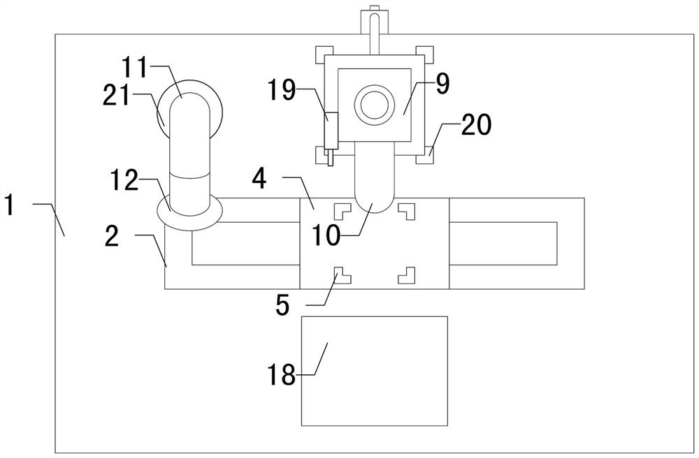
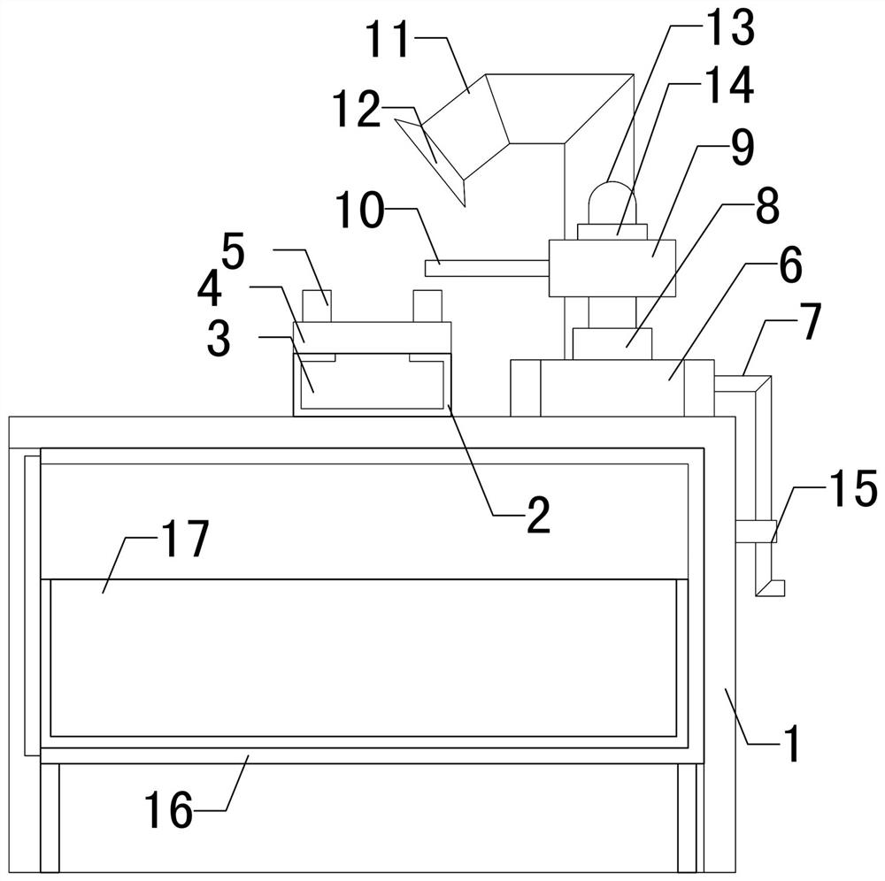
[0021] like Figure 1 to Figure 4 As shown, a deburring device for circuit breaker processing of the present invention includes a worktable 1, a moving device 3, a placing table 4, a lifter 6 and a retractor 9. The worktable 1 is provided with a moving frame 2, and a moving device 3 It can be movably installed on the moving frame 2, the placing table 4 is fixedly installed on the top of the moving device 3, the top of the placing table 4 is symmetrically provided with four groups of first fixing frames 5, and the lifter 6 is fixedly installed on the top rear of the workbench 1. 6. The rear end is provided with a wiring conduit 7, the top of the lifter 6 can be raised and lowered with a li...


PUM


Abstract

The invention relates to the technical field of circuit breaker machining, in particular to a deburring device for circuit breaker machining. The deburring device for circuit breaker machining, the automation degree of the device is conveniently improved, manpower is saved and time is shortened, the machining efficiency is improved, and the practicability and safety of the device are improved. The deburring device for circuit breaker machining comprises a workbench, a moving device, a placing table, a lifter and a telescopic device, a moving frame is arranged on the workbench, the moving device is movably installed on the moving frame, the placing table is fixedly installed at the top end of the moving device, four sets of first fixing frames are symmetrically arranged at the top end of the placing table, and the lifter is fixedly installed at the rear portion of the top end of the workbench. A wiring pipeline is arranged at the rear end of the lifter, a lifting rod is liftably arranged at the top end of the lifter, the telescopic device is fixedly mounted at the top end of the lifting rod, and a cutter is rotatably arranged at the front end of the telescopic device.

Description

technical field [0001] The invention relates to the technical field of circuit breaker processing, in particular to a deburring device for circuit breaker processing. Background technique [0002] A circuit breaker refers to a switch device that can close, carry and break current under normal circuit conditions and can close, carry and break current under abnormal circuit conditions within a specified time. Circuit breakers are divided into High-voltage circuit breakers and low-voltage circuit breakers, the distinction between high and low voltage is relatively vague, generally referred to as high-voltage electrical appliances above 3kV, circuit breakers can be used to distribute electric energy, start asynchronous motors infrequently, and protect power lines and motors. It can automatically cut off the circuit in the event of serious overload or short circuit and undervoltage. Its function is equivalent to the combination of a fuse switch and an overheating and underheating...

Claims


Application Information

Patent Timeline
IPC IPC(8): B23D79/00B23Q11/00
Inventor 王纪华
Owner 王纪华
Learn More