Automatic plate-shaped part feeding device and method for robot welding

A robot welding and automatic feeding technology, which is applied to auxiliary devices, welding equipment, conveyor objects, etc., can solve the problems of inability to realize automatic production, low production efficiency, and high manual labor intensity, so as to improve the level of mechanical automation and improve efficiency , Reduce the effect of manual labor intensity

Pending Publication Date: 2021-04-20
HARBIN BOILER
View PDF0 Cites 2 Cited by
  • Summary
  • Abstract
  • Description
  • Claims
  • Application Information

AI Technical Summary

Problems solved by technology

[0002] In coal-fired power plant boilers, horizontally arranged heating surface components such as horizontal low-temperature superheaters and horizontal low-temperature reheaters need to be suspended by hanging pipes. The hanging pipes are welded structures of pipes and plate-shaped parts. During the assembly process, it is necessary to manually place the plate-shaped parts into the corresponding positions of the pipe one by one, carry out manual loading, and then carry out subsequent decoration, welding and other processes. Due to the large number of plate-shaped parts, the production process of placing and loading The manual labor intensity is high, the production efficiency is low, and the automatic production cannot be realized

Method used


Image

  • Automatic plate-shaped part feeding device and method for robot welding
  • Automatic plate-shaped part feeding device and method for robot welding
  • Automatic plate-shaped part feeding device and method for robot welding

Examples


Embodiment 1

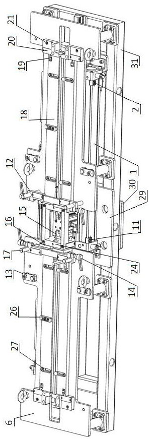
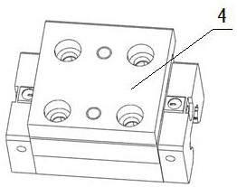
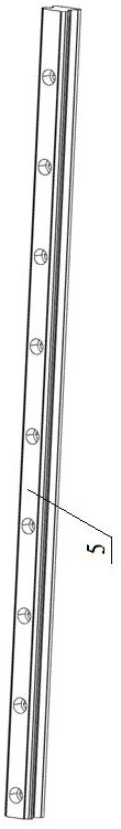
[0047] An automatic feeding device for plate-shaped parts for robot welding, which consists of: a support frame, a support plate 29 is fixed at the middle position above the support frame 31, and the support plate is connected to the guide rail 5 through screws, and the support plate A jacking cylinder 8 is fixed at the middle position of the guide rail, and a propulsion slider 4 is installed on the guide rail. The propulsion slider is connected with one end of the axial cylinder 1 through the connecting plate 3, and the axial cylinder is fixed on the On the support frame described above, a jacking block 23 is installed at the front end of the pushing slider, a jacking assembly 7 is connected above the jacking cylinder, and jacking blocks 9 and 2 are respectively installed on both sides of the jacking assembly. The adjustment plates 18 are arranged side by side in a group with grooves formed between them, and are respectively installed on the cover plate 6 by bolts. One end of ...

Embodiment 2

[0049] According to the automatic feeding device for plate-shaped parts for robot welding described in Embodiment 1, the lower part of the cover plate is connected to the support frame through a set of support columns 28, and the fixed frame 24 is installed in the middle of the support plate , positioning plates 12 are respectively installed on both sides of the fixed frame, and guide shafts 17 are installed at both ends of the plane on the positioning plate, and the side of the positioning plate is screwed to the adjustable position tightening handle 14, and the guide shafts are installed on the cover plate 6 on.

Embodiment 3

[0051] According to the automatic feeding device for plate-shaped parts for robot welding described in Embodiment 2, a group of plate-shaped parts are placed in the groove formed between the adjustment plate and the cover plate, and the bolts are passed on the cover plate Connected with the fixing device 13, two pneumatic connectors A22 are installed on the jacking cylinder, the pneumatic connector B32 is installed on the end of the axial cylinder, and the backing plate 30 is installed in the middle of the bottom of the support frame.


PUM


Abstract

The invention discloses an automatic plate-shaped part feeding device and method for robot welding. At present, plate-shaped parts need to be fed manually and then subjected to subsequent procedures in hanging pipe assembly, the number of the plate-shaped parts is large, the labor intensity is increased in the placing and feeding process, and the production efficiency is low. The device comprises a supporting frame (31), a supporting plate (29) is fixed to the middle of the upper side of the supporting frame and connected with a guide rail (5) through screws, a jacking air cylinder (8) is fixed to the middle of the supporting plate, a pushing sliding block (4) is installed on the guide rail and connected with one end of an axial air cylinder (1) through a connecting plate (3), the axial air cylinder is fixed to the supporting frame, a jacking block (23) is installed at the front end of the pushing sliding block, a jacking assembly (7) is connected to the upper side of the jacking air cylinder, jacking blocks (9) are installed on the two sides of the jacking assembly respectively, two adjusting plates (18) are arranged in a set side by side, and a groove is formed between the two adjusting plates. The invention is applied to the automatic plate-shaped part feeding device for robot welding.

Description

technical field [0001] The invention relates to the technical field of coal-fired power plant boilers, in particular to an automatic feeding device and method for plate-shaped parts used for robot welding. Background technique [0002] In coal-fired power plant boilers, horizontally arranged heating surface components such as horizontal low-temperature superheaters and horizontal low-temperature reheaters need to be suspended by hanging pipes. The hanging pipes are welded structures of pipes and plate-shaped parts. During the assembly process, it is necessary to manually place the plate-shaped parts into the corresponding positions of the pipe one by one, carry out manual loading, and then carry out subsequent decoration, welding and other processes. Due to the large number of plate-shaped parts, the production process of placing and loading The manual labor intensity is high, the production efficiency is low, and the automatic production cannot be realized. Contents of th...

Claims


Application Information

Patent Timeline
Patent Type & Authority Applications(China)
IPC IPC(8): B65G47/06B23K37/00
Inventor 刁旺战徐祥久李秋石王萍郭志成赵卫君曲瑞张宇危兆胜张德金杨红权
Owner HARBIN BOILER
Why Eureka
Try Eureka