Drainage structure for improving saline-alkali soil and other low-yield fields based on water conservancy improvement method

A water conservancy improvement and drainage structure technology, applied in water conservancy projects, soil drainage, application, etc., can solve the problems of large engineering volume, collapse of drainage ditches, time-consuming and other problems, and achieve the effect of reducing occupied area, avoiding collapse, and facilitating disassembly and cleaning

Inactive Publication Date: 2021-04-20
茆茜
View PDF7 Cites 0 Cited by
  • Summary
  • Abstract
  • Description
  • Claims
  • Application Information

AI Technical Summary

Problems solved by technology

[0005] The purpose of the present invention is to provide a drainage structure for improving low-yield fields such as saline-alkali land based on the water conservancy improvement method, so as to solve the problem that the slope instability of the drainage structure on the market will cause the collapse of the drainage ditch proposed by the above-mentioned background technology. Protection through sand-free concrete, concrete grids, etc. These require preliminary construction preparations, a large amount of engineering, and a certain amount of time.

Method used


Image

  • Drainage structure for improving saline-alkali soil and other low-yield fields based on water conservancy improvement method
  • Drainage structure for improving saline-alkali soil and other low-yield fields based on water conservancy improvement method
  • Drainage structure for improving saline-alkali soil and other low-yield fields based on water conservancy improvement method

Examples


Embodiment Construction

[0028] The following will clearly and completely describe the technical solutions in the embodiments of the present invention with reference to the accompanying drawings in the embodiments of the present invention. Obviously, the described embodiments are only some, not all, embodiments of the present invention. Based on the embodiments of the present invention, all other embodiments obtained by persons of ordinary skill in the art without making creative efforts belong to the protection scope of the present invention.

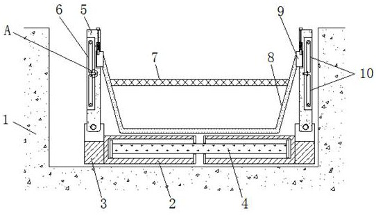
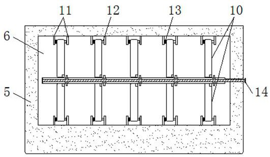
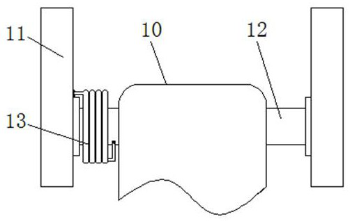
[0029] see Figure 1-8 , the present invention provides a technical solution: a drainage structure for improvement of low-yield fields such as saline-alkali land based on the water conservancy improvement method, including a sump 1, a horizontal plate 2, an installation plate 3, a connecting plate 4, a vertical plate 5, and an accommodating tank 6 , filter screen 7, rain cloth 8, connecting block 9, mounting rod 10, groove 101, fixed block 11, cross bar 12, to...


PUM


Abstract

The invention discloses a drainage structure for improving saline-alkali soil and other low-yield fields based on a water conservancy improvement method. The drainage structure comprises a water collecting tank, a connecting plate, a containing tank and a filter screen, wherein transverse plates are placed in the water collecting tank, mounting plates are fixed to the outer sides of the transverse plates through screws, the transverse plates are embedded into the outer sides of the left and right ends of the connecting plate, the interiors of the top ends of the mounting plates are connected with a vertical plate through movable shafts, the containing tank is formed in the outer side of the vertical plate, a mounting rod is placed in the containing tank, a transverse rod is in key connection to the interior of one end of the mounting rod in a penetrating mode, the front and rear ends of the transverse rod are respectively connected with a fixed block through bearings, the fixed block is connected with the vertical plate through screws, the bearings penetrate through the vertical plate, and a threaded rod is connected to the interior of the vertical plate. According to the drainage structure for improving the saline-alkali soil and other low-yield fields based on the water conservancy improvement method, the transverse plates and the vertical plate are arranged, and additionally, the transverse plates and the connecting plate form a sliding structure, so that the length of the transverse plates is convenient to adjust, and the transverse plates can be used for the water collecting tanks of different sizes.

Description

technical field [0001] The invention relates to the technical field of improving low-yield fields such as saline-alkali land, and specifically relates to a drainage structure for improving low-yield fields such as saline-alkali land based on a water conservancy improvement method. Background technique [0002] As the name implies, saline-alkali land means that there are many salt components inside the land, which will affect the normal growth of crops. At present, there are many ways to improve low-yield fields such as saline-alkali land in the market. The water conservancy improvement method is one of the many methods. The water conservancy improvement method is Flush the soil with water to reduce the salt content in the soil. When using the water conservancy improvement method, it is necessary to use a drainage structure to facilitate the drainage of water in the later stage. Although there are many types of drainage structures on the market, they are in There are still so...

Claims


Application Information

Patent Timeline
IPC IPC(8): E02B11/00E02B11/02E02B5/02E02B5/08
Inventor 茆茜
Owner 茆茜
Why Eureka
Try Eureka