Intermittent transmission gear and reciprocating intermittent transmission mechanism
A transmission gear and transmission mechanism technology, applied in the field of transmission, can solve the problems of incomplete gear mechanism movement and stop period adjustment, difficult to apply, etc.
- Summary
- Abstract
- Description
- Claims
- Application Information
AI Technical Summary
Problems solved by technology
Method used
Image
Examples
Embodiment 1
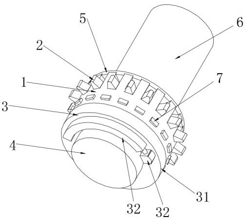
[0046] Such as Figure 1-8 shown, where figure 1 It is a schematic diagram of the overall structure after the intermittent transmission gear is assembled with the assembly shaft 6; figure 2 is the front schematic diagram of the intermittent transmission gear; image 3 for figure 2 A cross-sectional view along A-A; Figure 4 for image 3 The enlarged schematic diagram of area B in the center; Figure 5 is the explosion diagram of the intermittent transmission gear, in order to facilitate the clear display of the structure of the intermittent transmission gear, in Figure 5 Only one control device 7 and one pinion 2 are shown in ; Image 6 is a schematic diagram of the structure of gear 2; Figure 7 It is one of the state schematic diagrams of the intermittent transmission gear; Figure 8 It is the second state diagram of the intermittent transmission gear.
[0047] Such as Figure 4 with Figure 5 As shown, the intermittent transmission gear provided in this embodi...
Embodiment 2
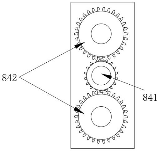
[0064] In order to adapt to special working conditions, this embodiment provides a reciprocating intermittent transmission mechanism, which can adjust the motion and rest period of the intermittent motion while performing the reciprocating intermittent motion.
[0065] Specifically, as Figure 9 As shown, the reciprocating intermittent transmission mechanism includes
[0066] The first moving mechanism 81, the first moving mechanism 81 includes a moving part 813, a first rack 811 and a second rack 812, the first rack 811 and the second rack 812 are respectively arranged on both sides of the moving part 813 , the first rack 811 and the second rack 812 can be fixedly installed with the moving part 813, or integrally formed with the moving part 813, and the tooth parts 23 of the first rack 811 and the second rack 812 face the moving part 813 respectively outside of
[0067] Two intermittent transmission gears as described in Embodiment 1, i.e. the first intermittent transmissio...
Embodiment 3
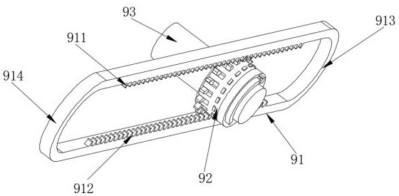
[0078] In order to adapt to special working conditions, this embodiment provides another reciprocating intermittent transmission mechanism, including
[0079] The second moving mechanism 91, the second moving mechanism 91 includes a third rack 911, a fourth rack 912, a first connecting member 913 and a second connecting member 914, the third rack 911 and the fourth rack 912 are symmetrically arranged, and the first connecting member 913, the third rack 911, the second connecting member 914, and the fourth rack 912 are sequentially connected to form a ring;
[0080] An intermittent transmission gear in Embodiment 1, that is, the third intermittent transmission gear 92, the third intermittent transmission gear 92 is located between the third rack 911 and the fourth rack 912, the teeth of the third intermittent transmission gear 92 23 Mesh with the third rack 911 and the fourth rack 912 respectively
[0081] The second driving mechanism 93 is connected with the intermittent tran...
PUM
 Abstract
Description
Claims
Application Information
 - R&D
- Intellectual Property
- Life Sciences
- Materials
- Tech Scout
- Unparalleled Data Quality
- Higher Quality Content
- 60% Fewer Hallucinations
Browse by: Latest US Patents, China's latest patents, Technical Efficacy Thesaurus, Application Domain, Technology Topic, Popular Technical Reports.
© 2025 PatSnap. All rights reserved.Legal|Privacy policy|Modern Slavery Act Transparency Statement|Sitemap|About US| Contact US: help@patsnap.com


