Pump suction type external circulation cooling device for lubricating oil in vibration box of hydraulic vibration pile driver

A technology of hydraulic vibration and extracorporeal circulation, applied in the direction of engine lubrication, engine components, lubricating parts, etc., can solve the problems of lubricating oil aging, thick shell, poor heat dissipation effect, etc.

Pending Publication Date: 2021-04-20
JIAXING UNIV
View PDF0 Cites 0 Cited by
  • Summary
  • Abstract
  • Description
  • Claims
  • Application Information

AI Technical Summary

Problems solved by technology

[0003] Both ends of the driving shaft and the driven shaft in the vibrating box of the hydraulic vibratory pile driver are installed with supporting bearings. The supporting bearings are installed in the vibrating box. The wheel produces a large centrifugal force, and the supporting bearings at both ends of the driving shaft and the driven shaft bear the action of this high-frequency centrifugal force. The friction of the bearings heats up seriously, and the heat is transferred to the lubricating oil in the vibrating box. Since the lubricating oil is sealed in the vibrating box, it cannot Effective heat dissipation causes the temperature of the lubricating oil to rise rapidly, making the supporting bearing poor in heat dissipation through the lubricating oil, and the bearing is easy to be damaged. At the same time, the lubricating oil temperature is too high and quickly ages, losing its lubricating effect, which further weakens the lubrication conditions of the bearing and other moving parts.
[0004] Generally speaking, the lubricating oil in the vibrating box of the pile driver mainly relies on the shell of the vibrating box to dissipate heat. The shell is very thick and the heat dissipation effect is poor. Some of them use cooling fans installed inside the vibrating box to dissipate heat, but the lubricating oil is still used. Enclosed in the vibration box, the heat dissipation effect is not ideal

Method used


Image

  • Pump suction type external circulation cooling device for lubricating oil in vibration box of hydraulic vibration pile driver
  • Pump suction type external circulation cooling device for lubricating oil in vibration box of hydraulic vibration pile driver
  • Pump suction type external circulation cooling device for lubricating oil in vibration box of hydraulic vibration pile driver

Examples


Embodiment Construction

[0039] The present invention will be further described in detail below with reference to the accompanying drawings and examples. The following examples are explanations of the present invention and the present invention is not limited to the following examples.

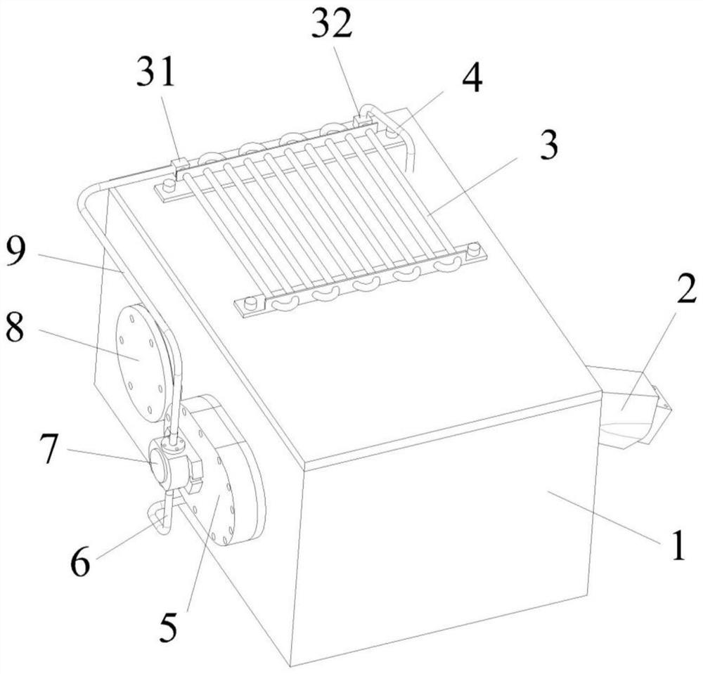
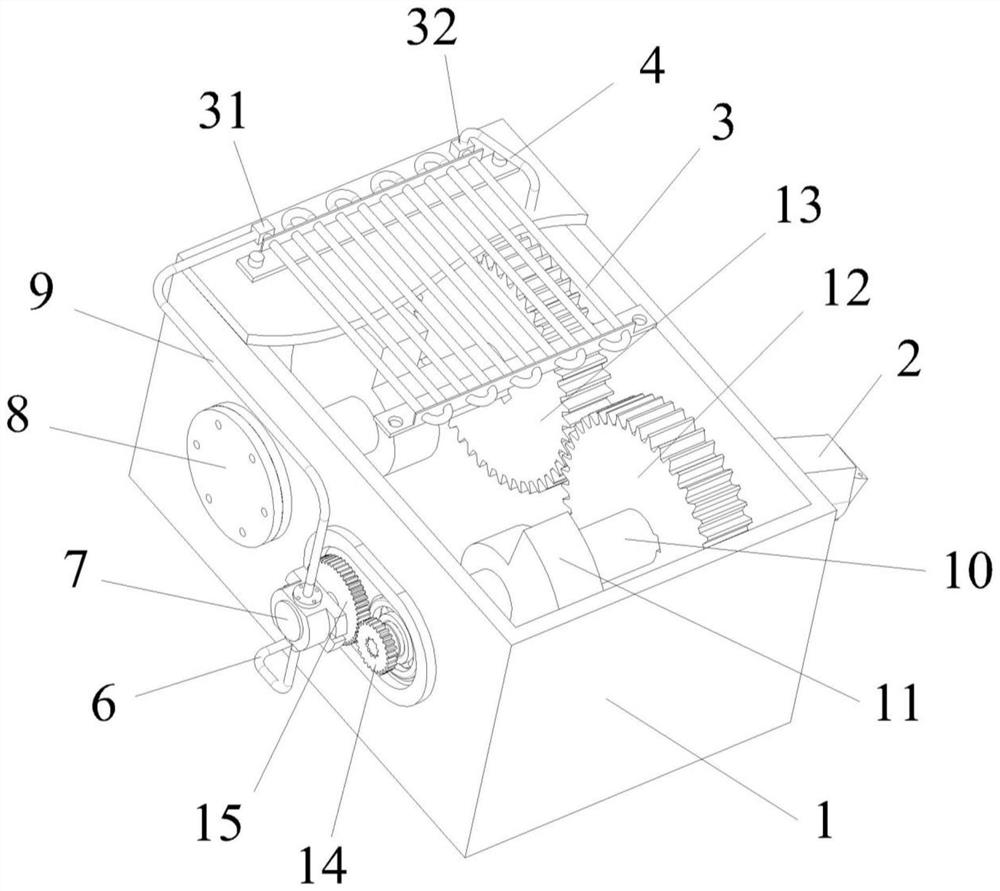
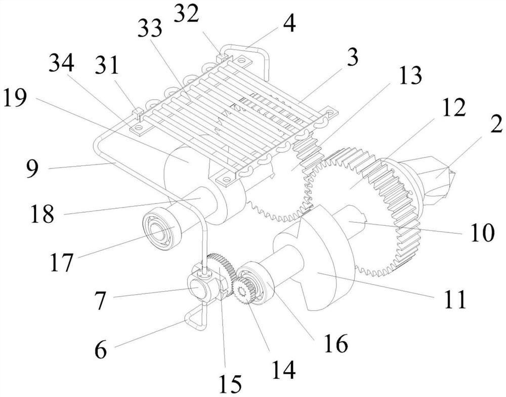
[0040] Such as Figure 1 to Figure 12 As shown, the pump-suction extracorporeal circulation cooling device for lubricating oil in the vibration box of the hydraulic vibration pile driver includes a vibration box 1, a radiator 3, a driving shaft 10, a driven shaft 18 and an oil suction pump 7; the radiator 3 is installed in the vibration box 1 on any shell surface; the driving shaft 10 is supported on the shell of the vibration box 1 through the first support bearing 16, and is fixed in the vibration box 1 through the first end cover 5; the driven shaft 18 passes through the second support bearing 17 Supported on the shell of the vibration box 1, fixed in the vibration box 1 through the second end cover 8; the hydrauli...


PUM


Abstract

The invention discloses a pump suction type external circulation cooling device for lubricating oil in a vibration box of a hydraulic vibration pile driver. The pump suction type external circulation cooling device is characterized in that an oil suction pump and a radiator are arranged outside the vibration box, and the oil suction pump is arranged on a first end cover or a second end cover; a driving wheel is arranged on a driving shaft or the driving wheel is arranged on a driven shaft, and a driven wheel is arranged on a rotary input shaft of the oil suction pump; and power of the driving shaft or the driven shaft is transmitted to the oil suction pump through meshing of the driving wheel and the driven wheel, the oil suction pump sucks the lubricating oil in the vibration box into the radiator for heat dissipation and cooling, and the lubricating oil flows back into the vibration box through an oil return pipe, so that cooling circulation of the lubricating oil outside the vibration box is realized. According to the pump suction type external circulation cooling device for the lubricating oil in the vibration box of the hydraulic vibration pile driver, the power is provided for the oil suction pump through rotation of the driving shaft or the driven shaft in the working process, the oil suction pump does not need to be externally connected with other power devices, external cooling circulation of the lubricating oil in the vibration box is achieved, the heat dissipation efficiency of the equipment is improved, and the service life of the equipment is prolonged.

Description

technical field [0001] The invention relates to the technical field of pile drivers, in particular to a circulating cooling device for lubricating oil in a vibration box of the pile driver. Background technique [0002] The vibration box of the hydraulic vibratory pile driver is equipped with a driving shaft and a driven shaft, and a synchronous gear with the same structural parameters is installed on the driving shaft and the driven shaft, and the driving shaft and the driven shaft are synchronized through the synchronous gear meshing transmission. For rotation, eccentric wheels are installed on both the driving shaft and the driven shaft. One end of the driving shaft is connected to the hydraulic motor. When the hydraulic motor drives the driving shaft to rotate, the driven shaft also rotates synchronously. The centrifugal force generated by the eccentric wheel on the driving shaft and the driven shaft drives the vibration box of the hydraulic vibration pile driver to vibr...

Claims


Application Information

Patent Timeline
Patent Type & Authority Applications(China)
IPC IPC(8): F16N39/02E02D7/18
Inventor 赵伟钱承宋玉来张海军欧阳青胡红生
Owner JIAXING UNIV
Why Eureka
Try Eureka