
Multi-axis deformation measuring instrument and installation method for concrete member

A measuring instrument and a technology for concrete, which are applied in the field of multi-axial deformation measurement of concrete members, can solve the problems that there is no overall simultaneous deformation analysis and research of concrete members, and less can measure the deformation in multiple directions at the same time.

Pending Publication Date: 2021-04-20
GUANGZHOU UNIVERSITY
View PDF0 Cites 0 Cited by
  • Summary
  • Abstract
  • Description
  • Claims
  • Application Information

AI Technical Summary

Problems solved by technology

Measuring and researching the shrinkage deformation of concrete has certain scientific value, research value and practical value, but at present, the measurement of the deformation of concrete components can only be measured on one side, and there is no analysis and research on the overall simultaneous deformation of concrete components
[0007] The change of concrete volume is carried out in multiple directions at the same time, and the current instruments for measuring the expansion and contraction deformation of concrete components can basically only measure the components in a certain direction, and rarely can measure the deformation of multiple directions at the same time. For example, the SP540 concrete shrinkage and expansion meter, the HSP540 concrete shrinkage and expansion meter, and the BCL-355 concrete shrinkage and expansion meter can only measure the deformation in the uniaxial direction.

Method used

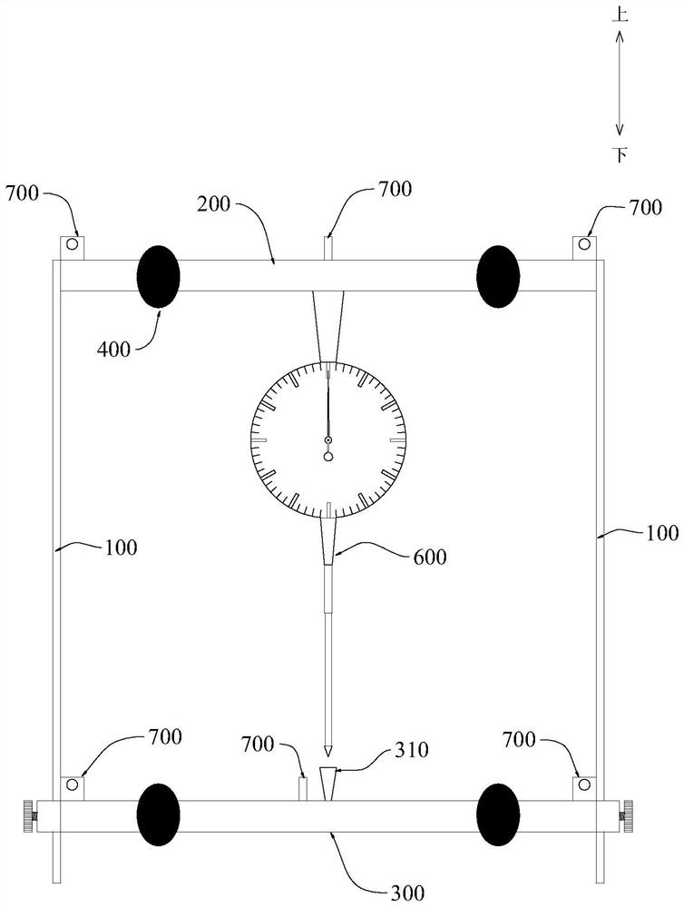
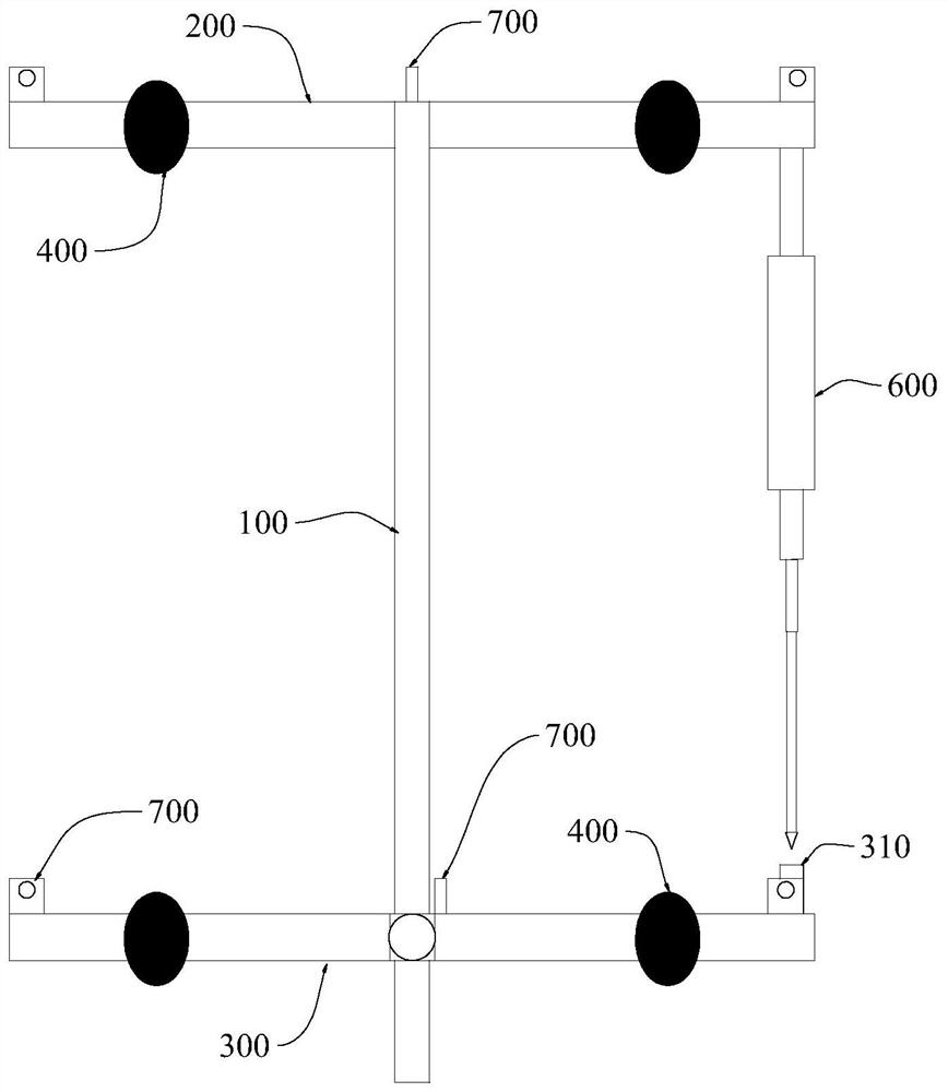
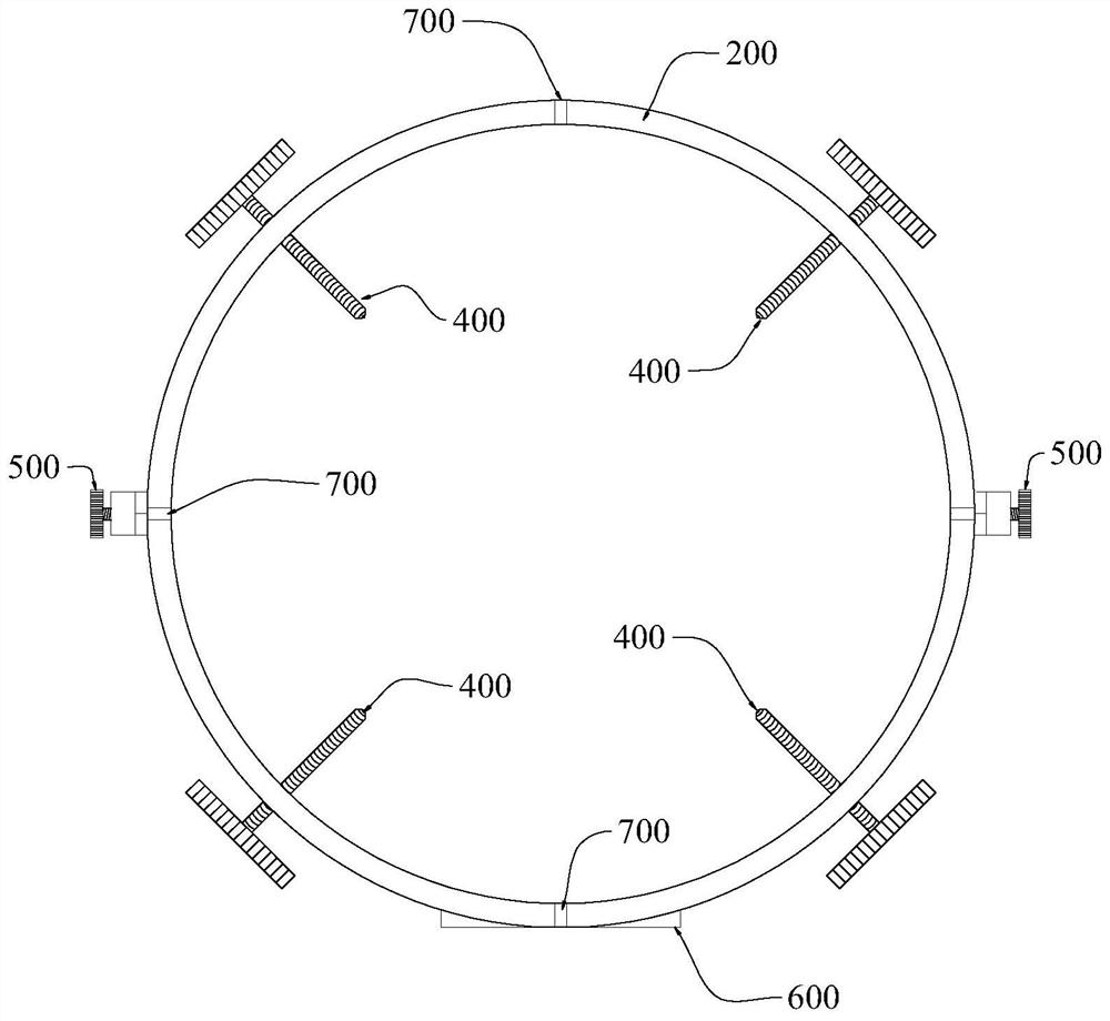

Image

  • Multi-axis deformation measuring instrument and installation method for concrete member
  • Multi-axis deformation measuring instrument and installation method for concrete member
  • Multi-axis deformation measuring instrument and installation method for concrete member

Examples


Embodiment Construction

[0039] This part will describe the specific embodiment of the present invention in detail, and the preferred embodiment of the present invention is shown in the accompanying drawings. Each technical feature and overall technical solution of the invention, but it should not be understood as a limitation on the protection scope of the present invention.

[0040] In the description of the present invention, it should be understood that the orientation descriptions, such as up, down, front, back, left, right, etc. indicated orientations or positional relationships are based on the orientations or positional relationships shown in the drawings, and are only In order to facilitate the description of the present invention and simplify the description, it does not indicate or imply that the device or element referred to must have a specific orientation, be constructed and operated in a specific orientation, and thus should not be construed as limiting the present invention.

[0041] I...


PUM


Abstract

The invention discloses a multi-axis deformation measuring instrument for a concrete member. The multi-axis deformation measuring instrument comprises at least two vertical support rods arranged at intervals, upper lantern rings and lower lantern rings, the upper lantern rings are arranged at the upper ends of the vertical support rods, the lower lantern rings are movably connected with the lower ends of the vertical support rods, the upper lantern rings and the lower lantern rings are each provided with a horizontal measurement displacement meter, the upper lantern rings are provided with vertical measurement displacement meters, the horizontal measurement displacement meters are arranged at intervals and face the center of the upper lantern rings, and the vertical measurement displacement meters are arranged towards the lower lantern rings, and the lower lantern rings are provided with abutting parts opposite to the vertical measurement displacement meters; a number of first fastening adjusting pieces are movably mounted on the upper lantern rings and the lower lantern rings correspondingly, and each first fastening adjusting piece is provided with an abutting part pointing to the periphery of the concrete member; and a number of second fastening adjusting pieces are movably mounted between the vertical support rods and the lower lantern rings. The deformation measuring instrument meets the experimental requirements of deformation in three directions, and can be widely applied to the technical field of civil engineering.

Description

technical field [0001] The invention relates to the technical field of multiaxial direction deformation measurement of concrete components, in particular to a multiaxial deformation measurement instrument and an installation method of concrete components. Background technique [0002] Concrete shrinkage refers to the volume reduction phenomenon that occurs in the initial stage of concrete setting or during the hardening process. Concrete shrinkage is generally divided into plastic shrinkage (also known as settlement shrinkage), chemical shrinkage (also known as self-shrinkage), drying shrinkage and carbonation shrinkage. Larger shrinkage of concrete will cause cracking of the concrete itself. [0003] During the setting process of concrete, due to the hydration and condensation of cement, it will cause the condensation of the volume of the concrete itself and the shrinkage caused by the evaporation and dissipation of free water inside the concrete itself. By analyzing the s...

Claims


Application Information

Patent Timeline
IPC IPC(8): G01B5/30G01N33/38G01B5/00
Inventor 何正铭金永耀赖勉亨黎承维王庆
Owner GUANGZHOU UNIVERSITY
Learn More