
Control motor for electric VVT

A technology of electric motor and casing, which is applied in the field of electric VVT control motor, which can solve the problems of poor sealing, motor influence, and affecting the practical life of the motor, etc.

Active Publication Date: 2021-04-20
MIANYANG FULIN PRECISION MACHINING
View PDF10 Cites 0 Cited by
  • Summary
  • Abstract
  • Description
  • Claims
  • Application Information

AI Technical Summary

Problems solved by technology

[0002] Existing motors, including brushless motors and brushed motors, are all connected by a casing and a flange to form an inner cavity, and a stator assembly and a rotor assembly are arranged in it; while the casing and the flange of the existing motor use Screw connection structure design, and the casing is made of metal, and the flange is connected with the casing by plastic or metal materials. However, the metal casing and the metal flange or the plastic flange are connected by screws to make the casing The seal between the shell and the flange is not good, so the external environment is easy to affect the inside of the motor and affect the practical life of the motor

Method used


Image

  • Control motor for electric VVT
  • Control motor for electric VVT
  • Control motor for electric VVT

Examples


Embodiment 1

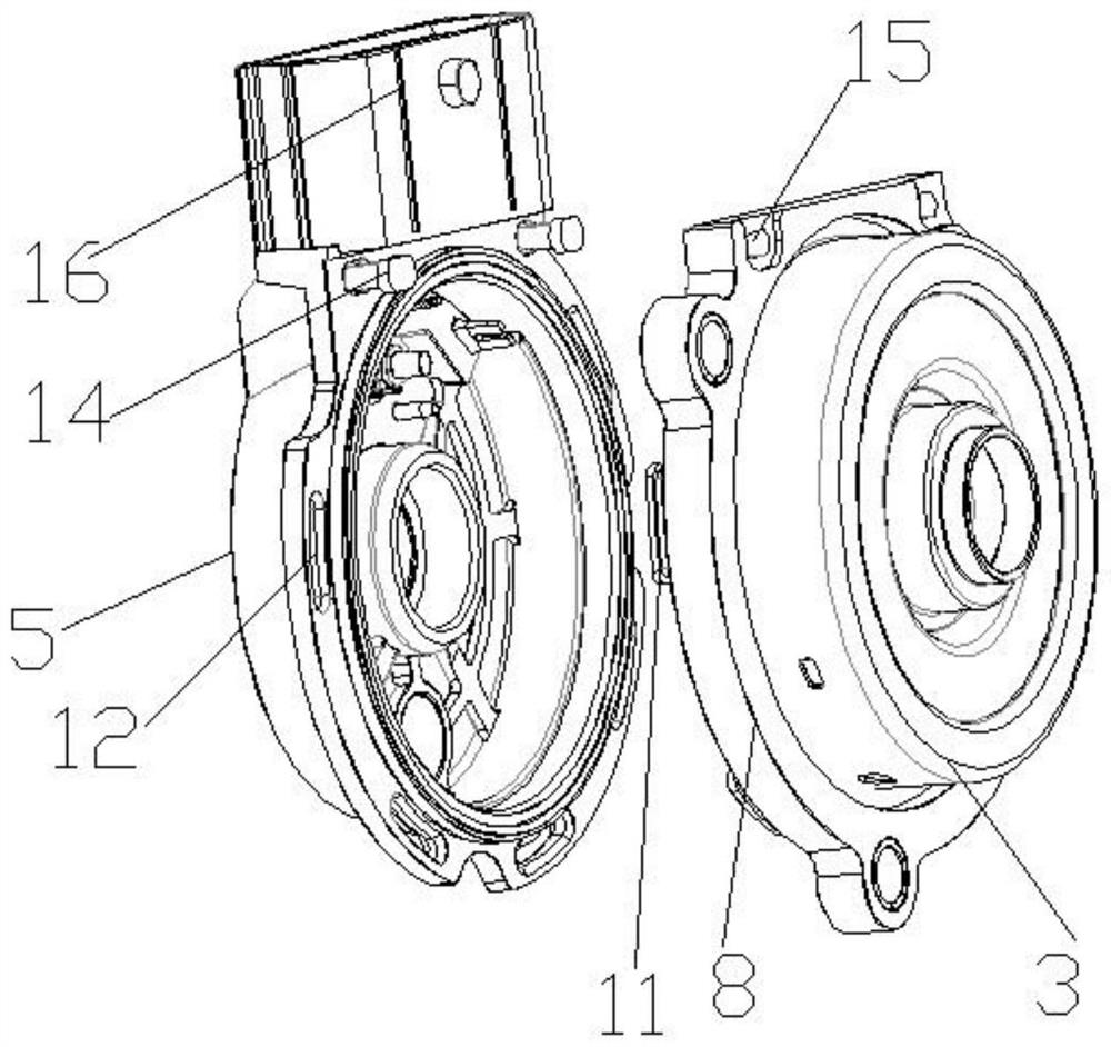
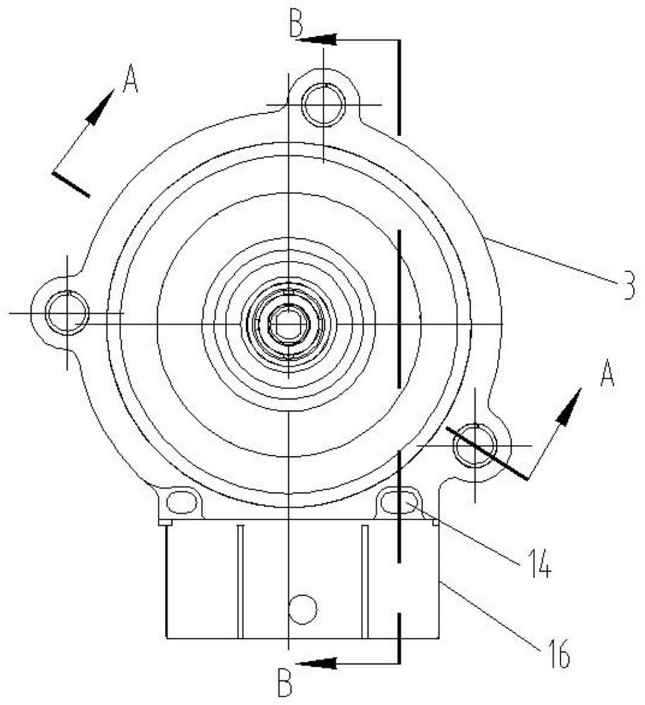
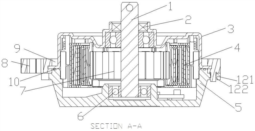
[0029] A control motor for an electric VVT, such as Figure 1-5 As shown, it includes a casing 3 and a plastic flange 5, the bottom of the casing 3 is an injection molding edging structure 8, and the outer periphery of the plastic flange 5 is integrally molded with a connector 16, and the plastic flange 5 A number of plastic bosses-14 are evenly distributed at the connection with the connecting machine 16, and the injection molding wrapping structure 8 at the bottom of the casing 3 is provided with a through hole-15 corresponding to the injection molding boss-14. Column one 14 is tightly connected with said through hole one 15; said injection molding encapsulation structure 8 is provided with several plastic convex columns two 11 along the circumferential direction, and said plastic flange plate 5 is provided with along the circumferential direction The second plastic post 11 corresponds to a plurality of second through holes 12, and the second plastic post 11 is tightly conne...

Embodiment 2

[0032] Based on the above-mentioned embodiment 1, the injection molding encapsulation structure 8 is provided with several through holes 12 along the circumferential direction, and the plastic flange 5 is provided with several plastic protrusions corresponding to the through holes 12 along the circumferential direction. The second post 11, the second plastic post 11 is firmly connected with the second through hole 12. In this embodiment, another structural form in which the injection molding wrapping structure 8 at the bottom of the casing and the plastic flange 5 are fastened and connected by setting plastic protrusions 11 and through holes 12 is described, that is: injection molding The edge structure 8 is provided with a plurality of through holes 12 in the circumferential direction, and the plastic flange 5 is provided with a plurality of plastic protrusions 11 corresponding to the through holes 12 along the circumferential direction, and the plastic protrusions 11 Realize...

Embodiment 3

[0034] Based on the above-mentioned embodiment 1 or 2, after the plastic boss 14 passes through the through hole 15, welding is used to realize the fast connection between the plastic boss 14 and the through hole 15, and the plastic boss 2 11 passes through the through hole. After the second hole 12, welding is used to realize the fastening connection between the second plastic post 11 and the second through hole 12; in this embodiment, the first plastic post 14 and the first through hole 15 as well as the second plastic post 11 and the through hole are specifically described. The fastening connection method of two 12, that is, the fastening connection between the plastic convex post 11 and the through hole 12 is realized by welding after the plastic post 11 passes through the through hole 12. Similarly, the plastic post 14 and the through hole 15 are also connected. Connect as above.


PUM


Abstract

The invention discloses a control motor for an electric VVT. The control motor for the electric VVT comprises a machine shell and a plastic flange plate, the bottom of the machine shell is of an injection molding edge covering structure, a connector is integrally arranged on the periphery of the plastic flange plate in an injection molding mode, and a plurality of first plastic protruding columns are evenly distributed at the joint of the plastic flange plate and the connector. A first through hole corresponding to the first plastic protruding column is formed in the injection molding edge covering structure at the bottom of the machine shell, and the first plastic protruding column is connected with the first through hole in a fastened mode; the injection molding edge covering structure is provided with a plurality of second plastic protruding columns in the circumferential direction, the plastic flange plate is provided with a plurality of second through holes corresponding to the plastic protruding columns in the circumferential direction, and the second plastic protruding columns and the second through holes are connected in a fastened mode. And reliable connection between the machine shell and the flange is ensured.

Description

technical field [0001] The invention belongs to the technical field of motors, including brushless motors and brushed motors, in particular to a control motor for electric VVT. Background technique [0002] Existing motors, including brushless motors and brushed motors, are all connected by a casing and a flange to form an inner cavity, and a stator assembly and a rotor assembly are arranged in it; while the casing and the flange of the existing motor use Screw connection structure design, and the casing is made of metal, and the flange is connected with the casing by plastic or metal materials. However, the metal casing and the metal flange or the plastic flange are connected by screws to make the casing The seal between the shell and the flange is not good, so the external environment is likely to affect the inside of the motor and affect the practical life of the motor. Contents of the invention [0003] The technical problem solved by the present invention is to provi...

Claims


Application Information

Patent Timeline
IPC IPC(8): H02K5/10H02K5/02H02K5/16
Inventor 向明朗王军邓猛刘强吴艳东
Owner MIANYANG FULIN PRECISION MACHINING
Learn More