
Tail gas scrubbing tower adopting gas-liquid separation membrane

A technology of tail gas scrubber and gas-liquid separation membrane, which is applied in the field of tail gas scrubber, can solve the problems of many scrubbing liquid components, poor gas-liquid separation effect, and inconvenient use, so as to improve the gas-liquid separation effect and realize gas-liquid separation Effect

Active Publication Date: 2018-09-21
昌和化学新材料(江苏)有限公司
View PDF7 Cites 0 Cited by
  • Summary
  • Abstract
  • Description
  • Claims
  • Application Information

AI Technical Summary

Problems solved by technology

[0002] The washing tower is a new type of gas purification treatment equipment, which is improved on the basis of the floating packing layer gas purifier, and is widely used in the pre- and post-processing work of industrial waste gas purification and dust removal; in the prior art There is usually no special gas-liquid separation device inside the exhaust gas scrubber, which results in poor gas-liquid separation after washing. The washed gas contains more washing liquid components, which is not convenient for the effective discharge of gas and affects the equipment. Service life; while the tail gas scrubber with a special gas-liquid separation device is installed inside, the gas-liquid separation device is expensive, and installed inside the tail gas scrubber, it is not easy to clean and maintain in the later stage, and it is inconvenient to use

Method used


Image

  • Tail gas scrubbing tower adopting gas-liquid separation membrane
  • Tail gas scrubbing tower adopting gas-liquid separation membrane
  • Tail gas scrubbing tower adopting gas-liquid separation membrane

Examples


Embodiment Construction

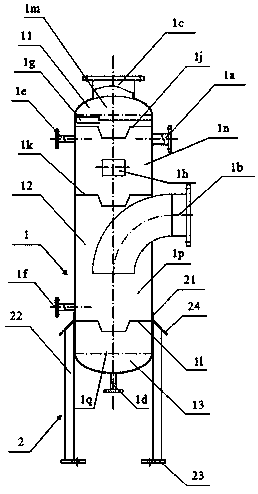
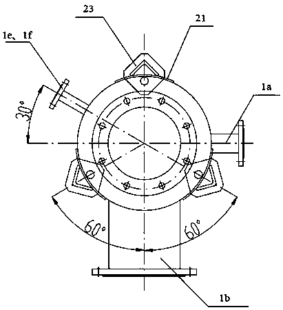
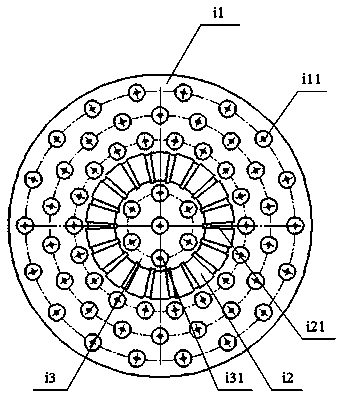
[0023] like Figure 1-4 As shown, a tail gas scrubber using a gas-liquid separation membrane is composed of a tower body 1 and a fixed part 2 located below the tower body 1. The tower body 1 includes a top 11 that is in the shape of a circular arc at the top, and a circular arc at the bottom. The arc-shaped bottom 13 and the hollow cylindrical middle part 12 between the top 11 and the bottom 13; the middle part 12 and the bottom 13 are connected by welding to ensure the connection strength and the internal tightness of the tower body. The middle part 12 and the top 11 are connected through the locking part 1g, so that the top 11 can be opened through the locking part 1g to replace and maintain the gas-liquid separation membrane inside the tower body; The membrane 1j, the second separation membrane 1k, and the third separation membrane 1l are separated into a top escape chamber 1m, a first separation chamber 1n, a second separation chamber 1p, and a bottom deposition chamber 1q...


PUM


Abstract

The invention relates to a tail gas scrubbing tower adopting gas-liquid separation membrane. The tail gas scrubbing tower is composed of a tower body (1) and a fixing part located on the lower portionof the tower body (1), the tower body (1) comprises a top portion (11), a bottom portion (13) and a middle portion (12), wherein the top portion (11) is in an arc cover shape and located on the upperportion of the tower body (1), the bottom portion (13) is in an arc cover shape and located on the lower portion of the tower body (1), and the middle portion (12) is in a hollow cylindrical shape and located between the top portion (11) and the bottom portion (13); the tail gas scrubbing tower is characterized in that the inner portion of the tower body (1) is separated into a top escaping cavity (1m), a first separation cavity (1n), a second separation cavity (1p) and a bottom sedimentary cavity (1q) through a first separation membrane (1j), a second separation membrane (1k) and a third separation membrane (1l) which are arranged sequentially from top to bottom; and the first separation membrane (1j), the second separation membrane (1k) and the third separation membrane (1l) are provided with micropores allowing gas to pass through but not allowing liquid to pass through; the gas-liquid separation membrane is adopted, the gas-liquid separation effect is improved, thereby being conductive to the effective discharge of gas, the cost is low, the later cleaning and maintenance are convenient, and the use is convenient.

Description

technical field [0001] The invention relates to the field of tail gas purification, in particular to a tail gas scrubber using a gas-liquid separation membrane. Background technique [0002] The washing tower is a new type of gas purification treatment equipment, which is improved on the basis of the floating packing layer gas purifier, and is widely used in the pre- and post-processing work of industrial waste gas purification and dust removal; in the prior art There is usually no special gas-liquid separation device inside the exhaust gas scrubber, which results in poor gas-liquid separation after washing. The washed gas contains more washing liquid components, which is not convenient for the effective discharge of gas and affects the equipment. Service life; while the tail gas scrubber with a special gas-liquid separation device is installed inside, the gas-liquid separation device is expensive, and installed inside the tail gas scrubber, it is not easy to clean and maint...

Claims


Application Information

Patent Timeline
Patent Type & Authority Applications(China)
IPC IPC(8): B01D53/18B01D47/00B01D46/54
CPCB01D46/543B01D47/00B01D53/18B01D2247/10B01D46/64
Inventor 胡全胜余新伟胡伟炳
Owner 昌和化学新材料(江苏)有限公司
Learn More