Milling cutter clamping equipment for mechanical manufacturing

A technology for mechanical manufacturing and clamping equipment, applied to milling machine equipment, milling cutters, manufacturing tools, etc., can solve the problems of troublesome installation and disassembly, influence of work flow, broken tools, etc., to facilitate installation and disassembly, and ensure machining accuracy. , to ensure stable and fixed effect

Inactive Publication Date: 2018-10-16
繁昌县通民机械制造有限公司
View PDF3 Cites 13 Cited by
  • Summary
  • Abstract
  • Description
  • Claims
  • Application Information

AI Technical Summary

Problems solved by technology

[0002] At present, the application of CNC machine tools has been popularized, and high-speed machining technology has also been developed rapidly. In order to achieve high-speed and high-precision machining, in addition to selecting high-performance tools during machining, the requirements for clamping equipment for milling cutters are also increasing. The higher the higher, the clamping equipment used in machinery manufacturing must have good clamping and rotating accuracy, but the clamping and rotating accuracy of ordinary milling cutter clamping equipment often fails to meet the requirements, and the milling cutter will shift, fall off and collapse. The phenomenon of knife breaking causes economic loss and personal danger. Therefore, the demand for milling cutter clamping equipment for machinery manufacturing is increasing
[0003] The general milling cutter clamping device for mechanical manufacturing only spirally clamps the milling cutter. This clamping method is unstable, and it is easy to cause the phenomenon of chipping and breaking of the cutter. This method is very dangerous. Dangerous, the ordinary milling cutter clamping device for mechanical manufacturing is troublesome to disassemble, replace and maintain. Since the milling cutter needs to be clamped very tightly during work, the clamping process is cumbersome and troublesome to install and disassemble, which directly affects the working time. Therefore, a milling cutter clamping device for mechanical manufacturing is proposed to solve the above problems

Method used


Image

  • Milling cutter clamping equipment for mechanical manufacturing
  • Milling cutter clamping equipment for mechanical manufacturing
  • Milling cutter clamping equipment for mechanical manufacturing

Examples


Embodiment Construction

[0021] The following will clearly and completely describe the technical solutions in the embodiments of the present invention with reference to the accompanying drawings in the embodiments of the present invention. Obviously, the described embodiments are only some, not all, embodiments of the present invention. Based on the embodiments of the present invention, all other embodiments obtained by persons of ordinary skill in the art without making creative efforts belong to the protection scope of the present invention.

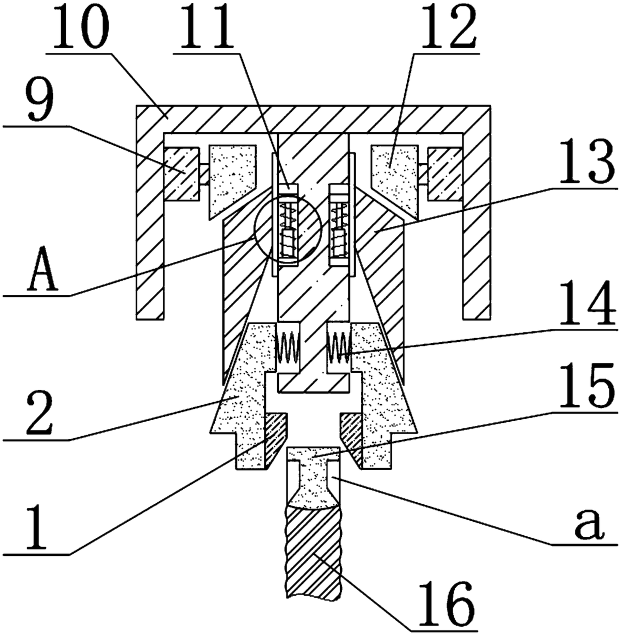
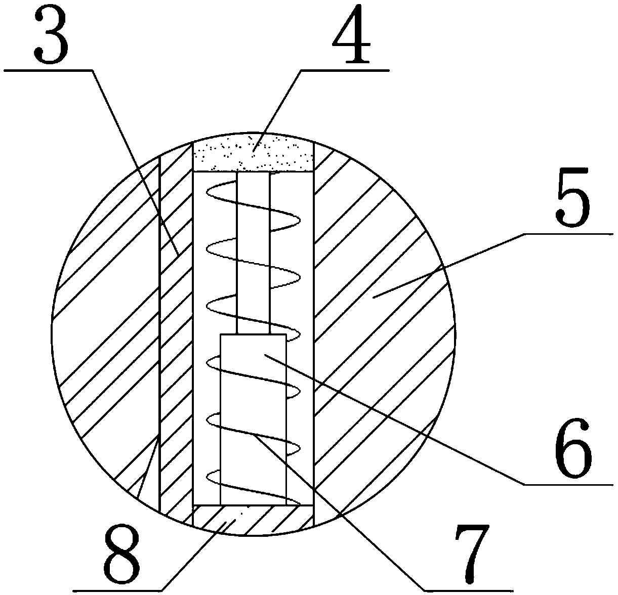
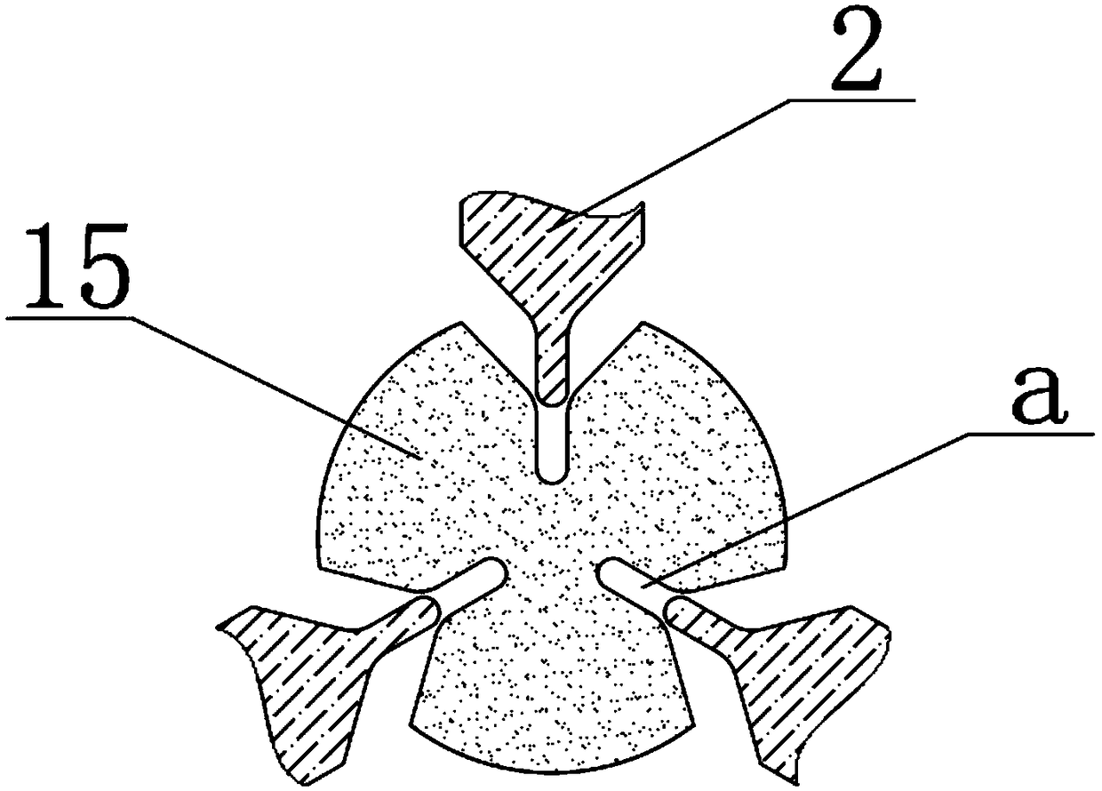
[0022] see Figure 1-5 , the present invention provides a technical solution:

[0023] A milling cutter clamping device for mechanical manufacturing, comprising a clamping block 2, a cylinder 9, a clamping shaft 5, a support frame 10 and a milling cutter 16, the center of the top of the support frame 10 is fixedly connected with a clamping shaft 5, the A first slide rail 8 is fixedly connected to the top of the clamping shaft 5, and a telescopic rod 6 is fixe...


PUM


Abstract

The invention relates to the technical field of mechanical equipment, in particular to milling cutter clamping equipment for mechanical manufacturing. The milling cutter clamping equipment comprises aclamping block, an air cylinder, a clamping shaft, a supporting frame and a milling cutter. The clamping shaft is fixedly connected to the center inside the top end of the supporting frame, a telescopic rod is fixedly connected to the top end of a first sliding rail, the outer side of the telescopic rod is sleeved with a first spring, a pressing block is fixedly connected to the top end of the telescopic rod, a clamping barrel is fixedly connected to the outer side of the sliding block, air cylinders are fixedly connected to the tops of the inner walls of the two sides of the supporting frame, driving blocks are fixedly connected to the tail ends of main shafts of the air cylinders, the clamping block is fixedly connected to the tail end of a second spring, a clamp block is fixedly connected to the inner side of the bottom end of the clamping block, a clamping groove is formed in the outer side of a fixing block, and the milling cutter is fixedly connected to the bottom end of the fixing block. The milling cutter clamping equipment is scientific and reasonable in structure, convenient to replace and maintain, capable of ensuring axial stability and fastening of a milling cutter shaft and worthy of being popularized, and has huge economic benefits and wide market demands.

Description

technical field [0001] The invention relates to the technical field of mechanical equipment, in particular to a milling cutter clamping device for mechanical manufacturing. Background technique [0002] At present, the application of CNC machine tools has been popularized, and high-speed machining technology has also been developed rapidly. In order to achieve high-speed and high-precision machining, in addition to selecting high-performance tools during machining, the requirements for clamping equipment for milling cutters are also increasing. The higher the higher, the clamping equipment used in machinery manufacturing must have good clamping and rotating accuracy, but the clamping and rotating accuracy of ordinary milling cutter clamping equipment often fails to meet the requirements, and the milling cutter will shift, fall off and collapse. The phenomenon of knife breaking causes economic loss and personal danger. Therefore, the demand for milling cutter clamping equipme...

Claims


Application Information

Patent Timeline
Patent Type & Authority Applications(China)
IPC IPC(8): B23C5/26
CPCB23C5/26
Inventor 不公告发明人
Owner 繁昌县通民机械制造有限公司
Why Eureka
Try Eureka