Atomizer having atomization cavity arranged in atomization core bracket

An atomizing cavity and atomizing core technology, applied in the field of atomizers, can solve the problems of ineffective waterproofing, uneven heating, and small heating area, and achieve the effects of improving user experience, uniform heating, and large atomization volume.

Pending Publication Date: 2021-04-23
HUIZHOU HAPPY VAPING TECH LTD
View PDF8 Cites 4 Cited by
  • Summary
  • Abstract
  • Description
  • Claims
  • Application Information

AI Technical Summary

Problems solved by technology

[0004] The atomizer of the existing electronic atomization equipment on the market includes an atomizing core, which generally includes a conductive liquid, and the material of the liquid conductive body is generally a long glass fiber rope or cotton rope. The atomizing core made of ceramics uses heating wire as the heating material. The heating wire is directly wound on the glass fiber rope or cotton rope or placed on the inner wall of the cylindrical ceramic. Due to the contact area between the heating wire and the liquid guide body Small, so there are problems of small heating area, small amount of atomization, and uneven heating
In addition, the existing atomizing cores all need to be installed in the atomizing cavity formed on the atomizing seat, and there is no atomizing cavity structure on the atomizing core body, so the vapor formed after the atomizing liquid is heated and evaporated Fog or aerosol is directly carried out by the airflow, and the small droplets that have not been atomized or condensed are also easily entrained by the airflow and can be sucked out without hindrance, which cannot effectively waterproof the fog

Method used


Image

  • Atomizer having atomization cavity arranged in atomization core bracket
  • Atomizer having atomization cavity arranged in atomization core bracket
  • Atomizer having atomization cavity arranged in atomization core bracket

Examples


Embodiment

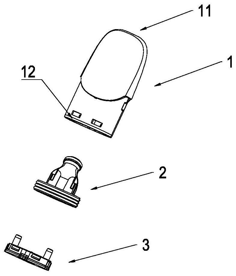
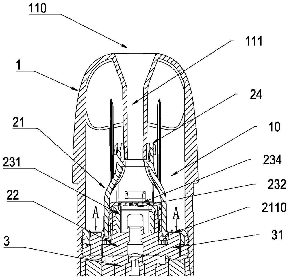
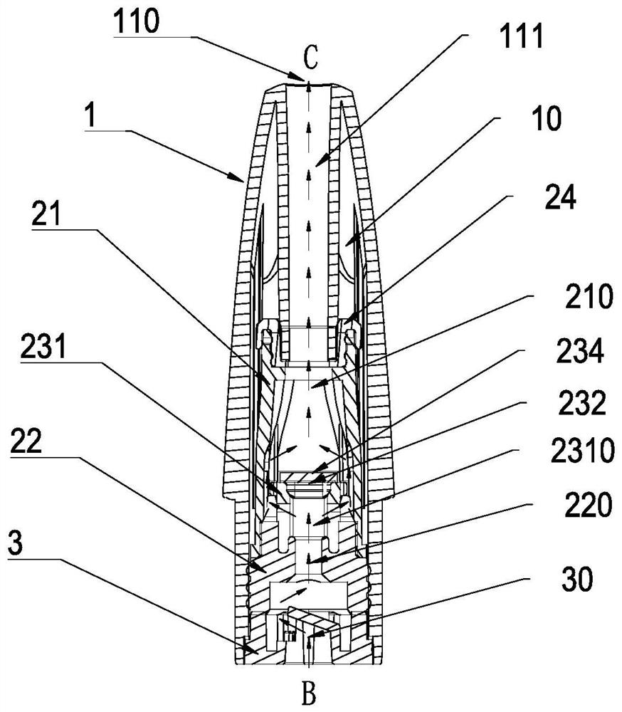
[0037]Such asFigure 1 - Figure 5 Design, an atomizing chamber of the present invention is provided in an atomizer in the atomizing core bracket, including the outer casing 1, the outer casing 1 including the nozzle end 11 and the connecting end 12, the suction end 11 is provided with suction port 110, suction 110 The bottom body is formed with a suction tube 111, and the connecting end 12 is provided with an opening 120, and the opening 120 is provided with a bottom cover 3 to block it, and the connection end 12 can be connected to the battery assembly to constitute an electron atomization device (not shown in the figure. ). The atomization assembly 2 is attached between the suction tube 111 and the bottom cover 3, and the atomization assembly 2 and the inner wall of the outer casing 1 are provided with a reservoir 10.

[0038]Such asFigure 6 - Figure 15 As shown, the atomizing assembly 2 includes a conventional throttle 21 and an atomizing seat 22 in which a cavity 22 are connected, a...


PUM


Abstract

The present invention discloses an atomizer having an atomization cavity arranged in an atomization core bracket. The atomizer comprises a shell, a suction port is formed in the suction nozzle end of the shell, a suction port pipe is downwards and integrally formed at the suction port, an opening is formed in the connecting end, a bottom cover is arranged at the opening to block the opening, and the connecting end can be connected with a battery assembly to form electronic atomization equipment. An atomization assembly is connected between the suction port pipe and the bottom cover, a liquid storage cavity is formed between the atomization assembly and the inner wall of the shell, the atomization assembly comprises a throttling cover and an atomization base which are connected up and down, cavities are formed in the throttling cover and the atomization base and used for installing an atomization core, the atomization core comprises a support, a heating piece and a liquid guide plate, and the support comprises a support plane and a support wall. The support wall is vertically arranged on the periphery of the lower portion of the support plane, the lower portion of the support plane and the support wall define an atomization cavity, an atomization through hole leading to the atomization cavity is downwards formed in the support plane, the heating piece is arranged on the support plane and the atomization through hole of the support plane, electrode leads are arranged at the two ends of the heating piece, and a liquid guide plate is tightly attached to the heating piece.

Description

Technical field[0001]The present invention relates to the technical field of electron atomizing apparatus, and more particular, the present invention relates to an atomizer disposed within the atomization core bracket.Background technique[0002]Electronic atomizing apparatus, generally includes battery packs and nebulizers, battery components are installed in the battery assembly, and the atomizer includes a heat generating unit, and the heat generating unit can atomize solution to the invertization of the solution. Fog, for useer inhaling in the mouth.[0003]Electronic atomization equipment specifically includes medical drug atomizing equipment, etc., the basic task is to provide a heating process, converting solutions such as an electron atomizing apparatus or a solution such as a vapor mist, an aerosol, vapor, and the like.[0004]The atomizer of the existing electron atomizing apparatus in the market, includes an atomization core, generally including a guide liquid, and material as ...

Claims


Application Information

Patent Timeline
Patent Type & Authority Applications(China)
IPC IPC(8): A24F40/10A24F40/40A24F40/42A24F40/46A61M11/00A61M15/06
CPCA24F40/10A24F40/40A24F40/42A24F40/46A61M11/00A61M15/06A61M15/0001
Inventor 林光榕郑贤彬
Owner HUIZHOU HAPPY VAPING TECH LTD
Why Eureka
Try Eureka