
Suction nozzle assembly and cleaning robot

A technology for components and dust collection chambers, applied in the field of cleaning robots, can solve the problems of uneven suction of the nozzle, low cleaning efficiency, and side leakage of dust particles.

Pending Publication Date: 2021-04-23
GREE ELECTRIC APPLIANCES INC
View PDF0 Cites 4 Cited by
  • Summary
  • Abstract
  • Description
  • Claims
  • Application Information

AI Technical Summary

Problems solved by technology

[0004] In order to solve the problem of uneven suction of the suction nozzle of the cleaning robot and low cleaning efficiency due to side leakage of dust particles, the invention provides a suction nozzle assembly and a cleaning robot. The invention solves the negative pressure inside the suction nozzle in the prior art The distribution and air flow movement are not conducive to the suction and transportation of dust particles on the ground, and dust particles are prone to leakage in the middle of the suction nozzle. A suction nozzle assembly is proposed, which improves the negative pressure distribution inside the suction nozzle and the airflow trajectory, and strengthens the vortex. The effect of the airflow improves the suction force of the suction pipe on the ground and the ability to transport dust particles accordingly, shortens the absorption time, avoids the leakage of dust particles caused by weak suction, makes the suction level more balanced everywhere, and improves the cleaning performance

Method used


Image

  • Suction nozzle assembly and cleaning robot
  • Suction nozzle assembly and cleaning robot
  • Suction nozzle assembly and cleaning robot

Examples


Embodiment Construction

[0028] In order to better understand the purpose, structure and function of the present invention, a suction nozzle assembly and a cleaning robot of the present invention will be further described in detail below in conjunction with the accompanying drawings.

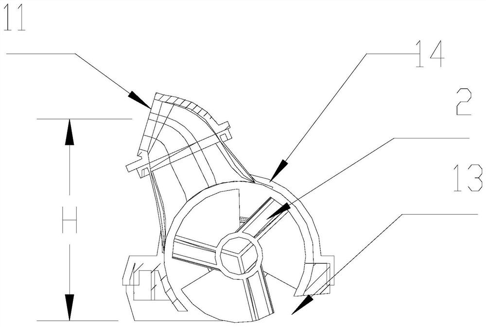
[0029] like figure 1 As shown, the nozzle assembly in the prior art includes a nozzle body 1, usually increasing the air outlet 11 of the nozzle body 1 to the height of the ground and the dust suction chamber 12 so that the average wind speed in the cavity is low, especially near the ground The wind speed is low, the suction to the ground is weak, and the dust particles continue to accumulate under the suction pipe, and it is too late to be lifted, which is prone to leakage.

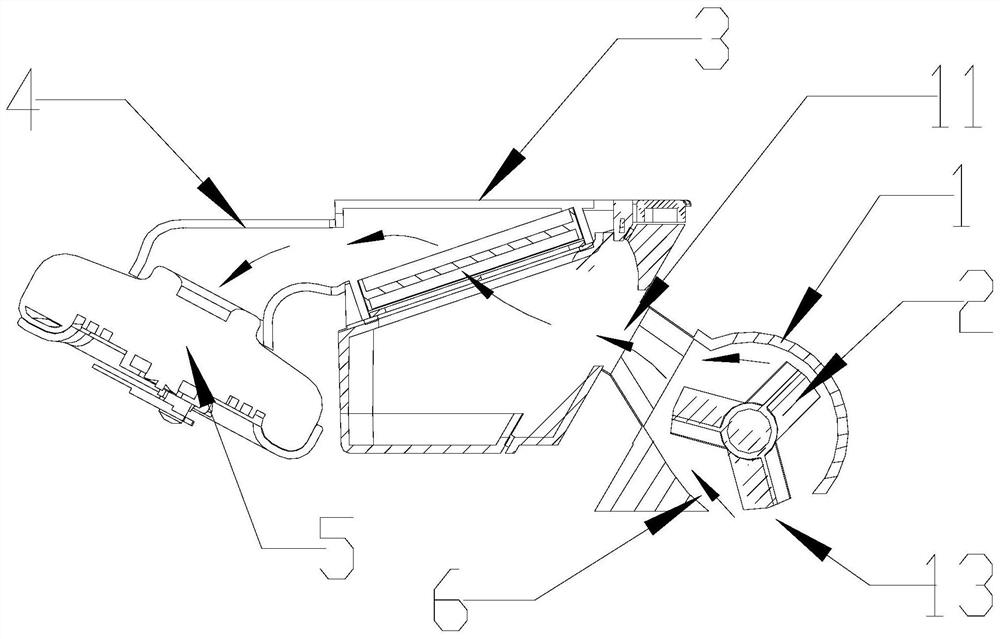
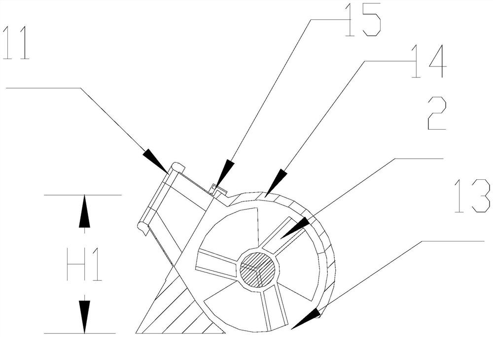
[0030] like figure 2 As shown, the present invention provides a nozzle assembly, including a nozzle body 1, a housing 15 is provided on the nozzle body 1, an inclined side wall is provided on the housing 15, and a suction nozzle body 1 and the h...


PUM


Abstract

The invention discloses a suction nozzle assembly, and the assembly comprises a suction nozzle body; a shell is arranged on the suction nozzle body, an inclined side wall is arranged on the shell, a dust collection cavity is formed by the suction nozzle body and the shell, an air inlet is formed in the bottom face of the suction nozzle body, and an air outlet is formed in the shell; airflow enters from the air inlet, flows through the dust collection chamber and is discharged from the air outlet, so the airflow flowing through the dust collection chamber is uniformly distributed. The invention further discloses a cleaning robot. The cleaning robot comprises the suction nozzle assembly. According to the suction nozzle assembly, the height from the air outlet to the ground is reduced, the average air speed in the dust collection cavity is increased, vortex airflow can be generated, the entrainment effect is enhanced, and therefore, the suction force to the ground and the negative pressure level are improved, the suction force below the air outlet is enhanced, and the dust particle conveying capacity is enhanced; transition areas from the two sides to the suction nozzle body are enlarged, so the suction force level is more balanced, and dust particle leakage caused by weak suction force is reduced.

Description

technical field [0001] The invention belongs to the field of cleaning robots, in particular to a suction nozzle assembly and a cleaning robot. Background technique [0002] The cleaning robot is a household appliance that uses a fan to generate high negative pressure to absorb dust particles on the ground. The suction nozzle is the entrance of the air duct pneumatic system of the whole machine, and it is also the part that gathers and absorbs dust particles. In order to improve the cleaning efficiency of the whole machine, the industry usually increases the speed of the fan, or chooses a larger fan to increase the air volume and air pressure of the pneumatic system, but the energy consumption and noise will also increase accordingly. [0003] When the wind speed close to the ground in the cavity of the suction nozzle is greater than the suspension speed of the dust particles, the dust particles can be lifted up, and the flow velocity under the suction pipe gradually decrease...

Claims


Application Information

Patent Timeline
IPC IPC(8): A47L9/04A47L9/28
Inventor 梁文龙柳洲林海利梁浩饶长健
Owner GREE ELECTRIC APPLIANCES INC
Learn More