Underwater chain stopper

A technology for chain stoppers and anchor chains, which is applied to ships and other directions, and can solve the problems of not being able to meet the needs of semi-submersible ships, and not being able to adapt to ships' water and underwater chain stops at the same time

Active Publication Date: 2021-04-23
WUHAN MARINE MACHINERY PLANT +1
View PDF9 Cites 0 Cited by
  • Summary
  • Abstract
  • Description
  • Claims
  • Application Information

AI Technical Summary

Problems solved by technology

[0003] The purpose of the present invention is to overcome the problems existing in the prior art that the gate blades need to be opened and closed manually, and cannot simultaneously adapt to the ship's water and underwater chain stop, and cannot meet the use requirements of semi-submersible ships, and provides an automatic control gate Knife opening and closing, and can be adapted to underwater and underwater two working conditions of the underwater chain stopper

Method used


Image

  • Underwater chain stopper
  • Underwater chain stopper
  • Underwater chain stopper

Examples


Embodiment 1

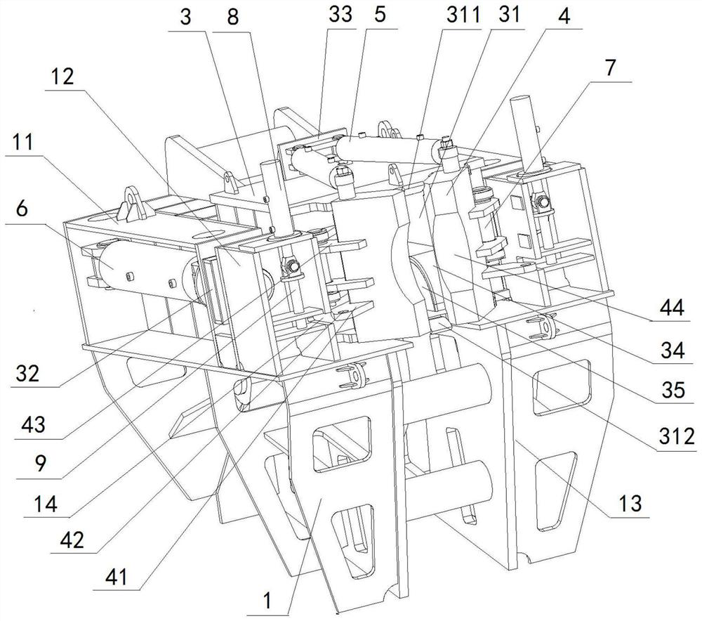
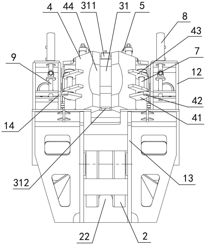
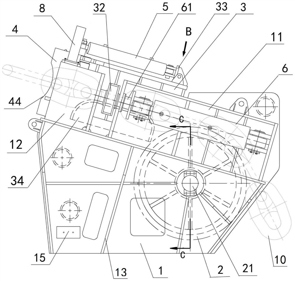
[0092] The underwater chain stopper includes a chain stopper bracket 1, a roller 2 and a brake knife holder 3, the roller 2 and the brake knife holder 3 are all arranged in the middle of the chain stopper bracket 1, and the roller 2 is located on the brake knife holder 3, the front side of the switch blade frame 3 is provided with two opposite switch blades 4, the switch blades 4 rotate with the switch blade frame 3 through the rotating pin 7, and the roller 2 connects with the chain stop bracket through the roller shaft 21 1 rotating fit; the middle part of the knife holder 3 is provided with an anchor chain channel 31; the left and right sides of the knife holder 3 are symmetrically provided with two tensioning oil cylinders 6, and the cylinder body of the tensioning oil cylinder 6 and The chain puller support 1 is fixedly connected, and the piston rod of the tensioning cylinder 6 is in transmission cooperation with the knife holder 3 through the knife holder connecting block...

Embodiment 2

[0094] Embodiment 2 is basically the same as Embodiment 1, and its difference is:

[0095] The chain stop bracket 1 includes a bottom bracket 13, two tension cylinder brackets 11 and two latch mechanisms 12, and the two tension cylinder brackets 11 are symmetrically fixed on the left and right sides of the top of the bottom bracket 13, The two latch mechanisms 12 are symmetrically fixed on the left and right sides of the top of the bottom bracket 13; the latch mechanism 12 is located on the front side of the blade holder connecting block 32, and the tension cylinder bracket 11 is located on the blade holder connecting block. 32, the tension cylinder bracket 11 is fixedly provided with a tension cylinder 6, the piston rod of the tension cylinder 6 is fixedly connected with one end of the push pin 61, and the other end of the push pin 61 is sequentially connected with The outer wall of the oil cylinder bracket 11 and the outer wall of the latch mechanism 12 are slidably matched,...

Embodiment 3

[0097] Embodiment 3 is basically the same as Embodiment 2, and its difference is:

[0098] The push pin 61 includes a first cylinder 611 and a second cylinder 612 integrally arranged, the first cylinder 611 and the second cylinder 612 are arranged coaxially, and the diameter of the first cylinder 611 is larger than that of the second cylinder The diameter of the body 612; one end of the first cylinder 611 is fixedly connected with the tensioning oil cylinder 6, the other end of the first cylinder 611 is fixedly connected with one end of the second cylinder 612, and the other end of the second cylinder 612 One end passes through the knife holder connecting block 32 and the spacer 613 in turn and is fixedly connected with the shaft end retaining ring 614; 32 through the spacer 613 and the shaft end retaining ring 614 limit fit; the first column 611 slides with the outer wall of the tension cylinder bracket 11 through the second water lubricated bearing 62, and the spacer 613 pas...


PUM


Abstract

An underwater chain stopper comprises a chain stopper support, a roller and a switch blade frame, the switch blade frame is arranged in the middle of the chain stopper support, the roller is arranged on the rear side of the switch blade frame, and two switch blades are arranged on the front side of the switch blade frame. The roller is positioned in the middle of the chain stopper bracket, and is rotationally matched with the chain stopper bracket through a roller shaft; an anchor chain channel is arranged in the middle of the knife switch frame. The left side and the right side of the knife switch frame are each provided with a tensioning oil cylinder, cylinder bodies of the tensioning oil cylinders are fixedly connected with the chain stopper support, and piston rods of the tensioning oil cylinders are in transmission fit with the knife switch frame through knife switch frame connecting blocks. Two knife switch overturning oil cylinders are symmetrically arranged at the top of the knife switch frame, cylinder bodies of the knife switch overturning oil cylinders are fixedly connected with the knife switch frame, and piston rods of the knife switch overturning oil cylinders are in transmission fit with the knife switches on the corresponding sides of the knife switch overturning oil cylinders. According to the underwater chain stopper, the turnover oil cylinder automatically controls the switch blade to be opened and closed, operation is safer and more convenient, and underwater work can be well adapted.

Description

technical field [0001] The invention relates to an anchor chain clamping device, in particular to an underwater chain catcher, which is particularly suitable for clamping the anchor chain after the ship sails or anchors. Background technique [0002] The chain catcher is mainly used to clamp the anchor chain after the ship sails or breaks down. After the anchor breaks down, the chain catcher on the brake can transmit the pulling force of the anchor chain to the hull so that the windlass is not under stress; when sailing, the chain catcher Bear the weight of the anchor and part of the anchor chain to ensure that the anchor is always fixed at the anchor hole and avoid collision between the anchor and the anchor hole. Therefore, the rationality of its structure is directly related to the safety performance of the ship. At present, most of the commonly used chain stops need to be manually opened and closed, which is inconvenient to use; The ship's water and underwater chain sto...

Claims


Application Information

Patent Timeline
Patent Type & Authority Applications(China)
IPC IPC(8): B63B21/18
CPCB63B21/18
Inventor 白宗陈旭东张雷张勇勇盛景乔李邦辉明国军曾维军郑晓勋
Owner WUHAN MARINE MACHINERY PLANT
Why Eureka
Try Eureka