

Wood Wall Panel Mounting System
A technology for installation system and wall panels, applied in covering/lining, construction, building construction, etc., can solve the problems of easy aging and corrosion of nail holes, affecting the appearance of nail holes, scrapping of wooden wall panels, etc., and achieve construction efficiency High, beautiful installation effect, small installation loss
- Summary
- Abstract
- Description
- Claims
- Application Information
AI Technical Summary
Problems solved by technology
Method used
Image

Examples
Embodiment 1
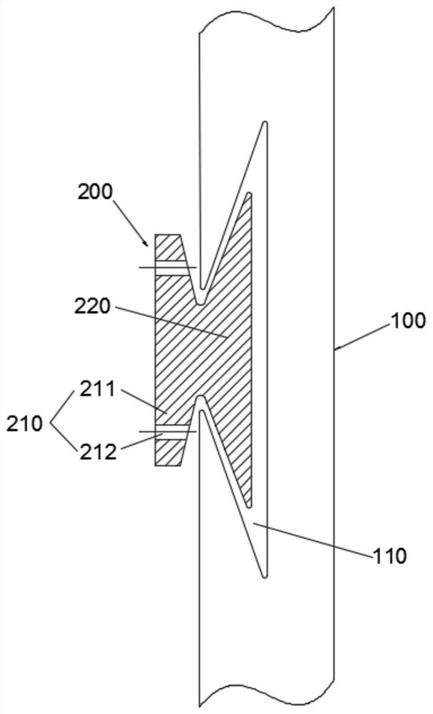
[0042] Example 1: Reference figure 1A wooden wallboard installation system shown includes a wooden wallboard 100 and a fastener 200, wherein the wooden wallboard 100 is any pure solid wood wallboard product (such as a pine wallboard) in the prior art, and its specification is 28mm (thickness)×198mm (width)×4185mm (length), the fastener 200 is an integrally formed metal alloy profile, or a high-density polypropylene profile formed by hot-melt injection molding.
[0043] The back of the wooden wallboard 100 is provided with multiple grooves 110 along its width direction. The tenon groove 110 can be provided on both sides of the wooden wallboard 100 in the width direction, and can also be set through the width direction of the wallboard 100 . The groove width at the groove bottom of the tenon groove 110 is greater than the groove width at its opening. Preferably, the tenon groove 110 is a dovetail groove, and the wedge angle of the tenon groove 110 is 18-22°. For example, the b...
Embodiment 2
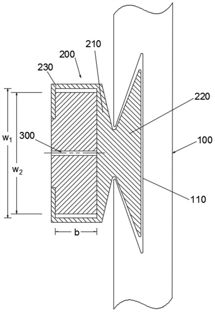
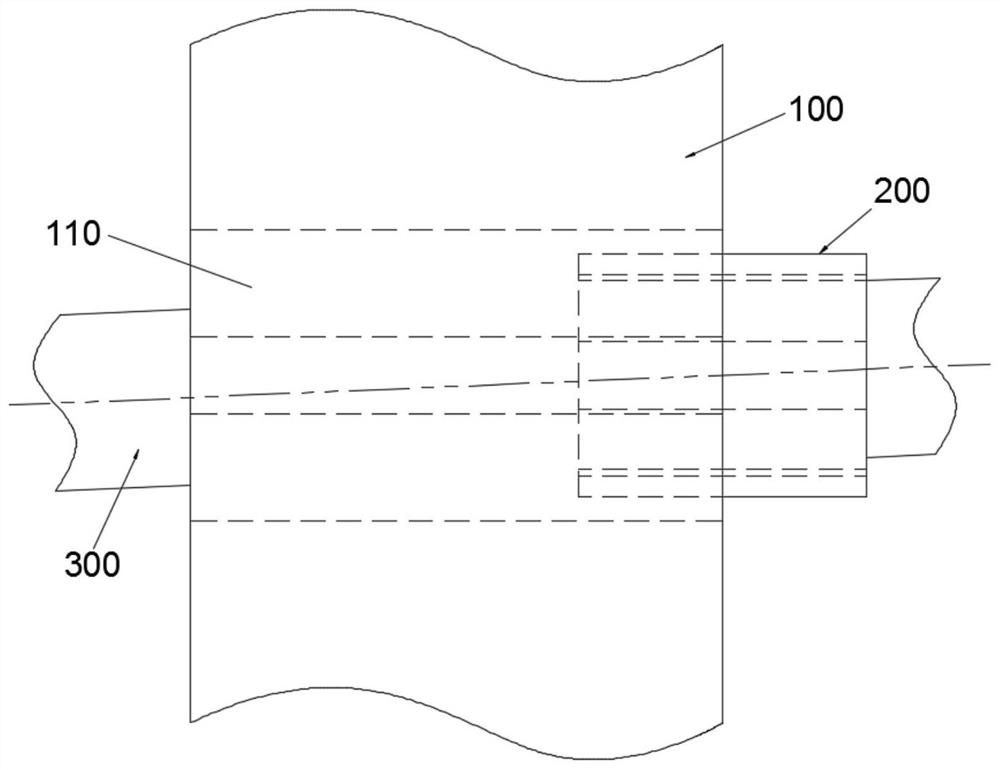
[0048] Embodiment 2: the difference between embodiment 2 and embodiment 1 is that, refer to figure 2 As shown, this wooden wall panel installation system also includes a keel 300, and both the fastener 200 and the keel 300 are high-density polypropylene profiles formed by hot-melt injection molding.
[0049] The fastener 200 also includes a sliding seat 230 fixedly connected with the fixing seat 210 . In this embodiment, the sliding seat 230 is composed of a pair of "L"-shaped clips, and the back side of the keel 300 along its widthwise edge is formed with a step for the clips and ends of the "L"-shaped clips. The sliding seat 230 is sleeved on the keel 300 so that the fastener 200 is installed on the keel 300 , and the fastener 200 slides along the length direction of the keel 300 through the sliding seat 230 .
[0050] In the technical solution of this embodiment, the fastener 200 is pre-sleeved on the keel 300 through the setting of the sliding seat 230 . Taking the vert...
Embodiment 3
[0054] Embodiment 3: the difference between embodiment 3 and embodiment 2 is that, refer to Figure 4 As shown, this wooden wall panel installation system includes multiple sets of installation structures consisting of a fastener 200 and a keel 300 .
[0055] The sliding seat 230 includes a sliding chamber 231 and a connecting chamber 232 arranged along its axial direction and communicated with each other. The keel 300 includes a connecting section 310 , a fixed section 320 and a sliding section 330 arranged along its axial direction and connected to each other in sequence. The inner diameter of the sliding cavity 231 and the connecting cavity 232 in the thickness direction are equal, and the inner diameter in the width direction w 3 Then compared with the inner diameter w of the connecting cavity 232 in the width direction 4 2 to 5 mm larger (for example, 4 mm). The widths of the connecting section 310, the fixed section 320, and the sliding section 330 are all equal, combi...
PUM
 Abstract
Description
Claims
Application Information