

Ejector and manufacturing method thereof
A technology of injectors and nozzles, which is applied in the field of injectors and its manufacturing, and can solve problems such as deformation and drop
- Summary
- Abstract
- Description
- Claims
- Application Information
AI Technical Summary
Problems solved by technology
Method used
Image

Examples
no. 1 example
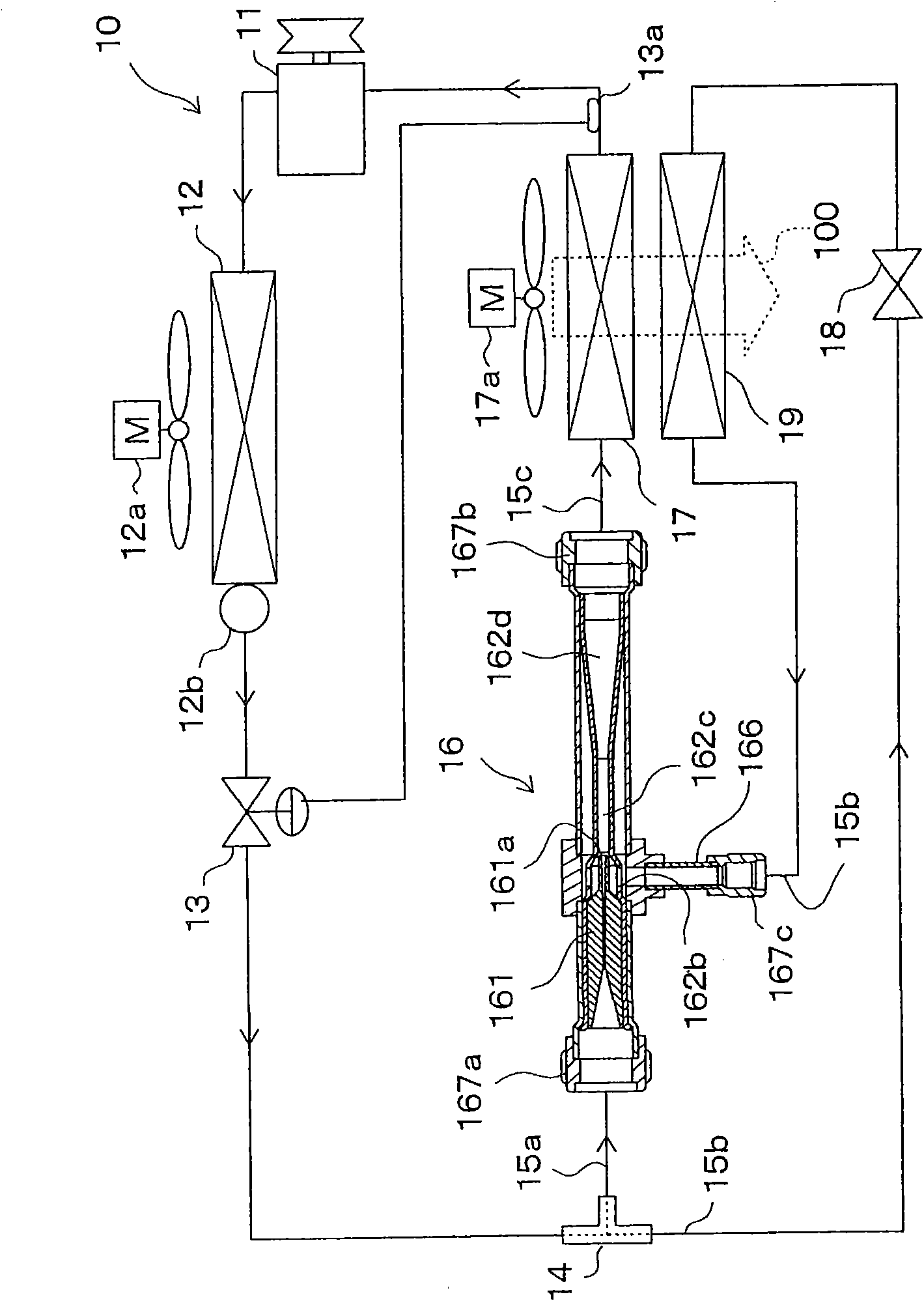
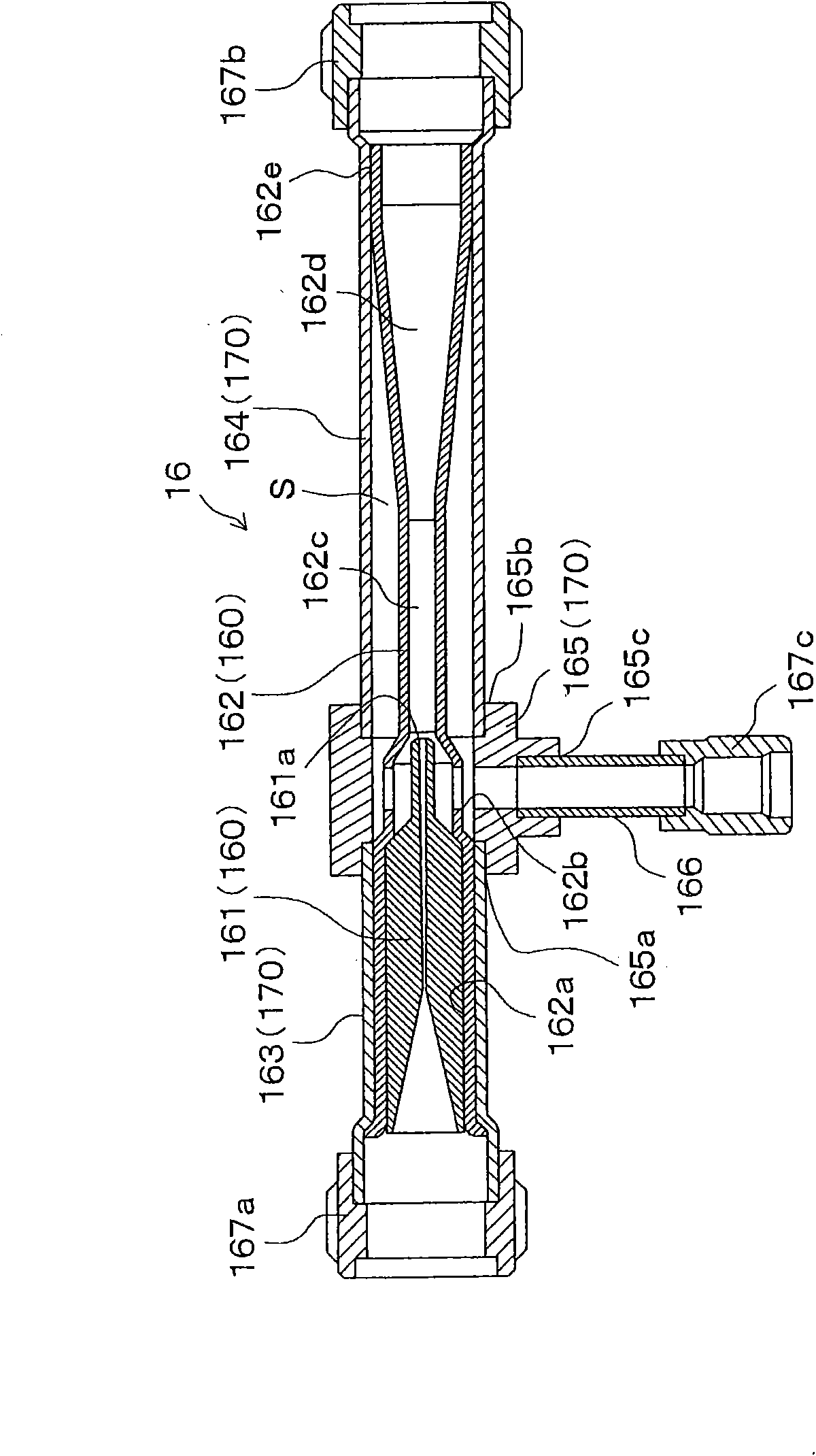
[0035] The first embodiment of the present invention can refer to Figure 1 ~ Figure 3 A description is made as follows. According to this embodiment, the ejector refrigeration cycle 10 is applied to a vehicle air-conditioning system, and the ejector refrigeration cycle 10 includes an ejector 16 . figure 1 The entire structure of the ejector refrigeration cycle 10 is schematically shown. In the ejector refrigeration cycle 10, the compressor 11 sucks a refrigerant (fluid), and compresses the sucked refrigerant. The compressor 11 is rotated by a driving force, for example, transmitted from an automobile engine (not shown) through an electromagnetic clutch and a belt.
[0036] The compressor 11 may be a variable displacement compressor or a fixed displacement compressor. In the case of a variable displacement compressor, the refrigerant delivery rate can be adjusted by changing the displacement of the variable displacement compressor. In the case of a fixed-displacement compr...
no. 2 example
[0095] In the first embodiment, the first pipe joint 167 a was described as an example of the connection portion of the injector 16 . In contrast, according to the second embodiment, as Figure 4 As shown, the connecting portion of the injector 16 includes a flange 167d formed as a fastening member at the other end portion (upstream end portion) of the first cover 163, the other end portion of the first cover 163 Opposed to the one end portion (downstream end portion) of the first cover 163 connected to the module 165 . Also, a flange 153 is formed at a connection end portion (downstream end portion) of the first refrigerant pipe 15a. The flange 167d of the first cover 163 and the flange 153 of the first refrigerant pipe 15a are connected together to make a connection between the first cover 163 and the first refrigerant pipe 15a.
[0096] Figure 4 is a partial axial cross-sectional view of injector 16 of the present embodiment. exist Figure 4 In , components similar to...
no. 3 example
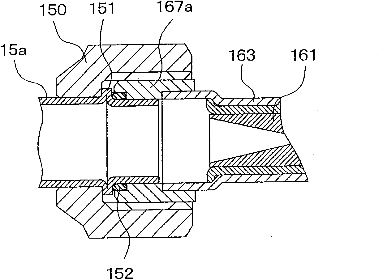
[0100] In the first embodiment, the O-ring 152 is interposed between the first pipe joint 167a and the first refrigerant pipe 15a. On the contrary, in the third embodiment of the present invention, as Figure 5 As shown, the O-ring is omitted, and a metal seal is provided to limit refrigerant leakage through the gap between the first refrigerant tube 15a and the first pipe joint 167a. Figure 5 is a partial axial cross-sectional view of injector 16 of the present embodiment.
[0101] Specifically, the expansion portion (branch portion) 155 is formed at the connection end portion (downstream end portion) of the first refrigerant tube 15a. The expansion portion 155 is fixed between the nut 150 and the first pipe joint 167a. The rest of the structure of the injector 16 is the same as that of the first embodiment.
[0102] Even when the gap between the first refrigerant pipe 15a and the first pipe joint 167a is sealed in the above-described manner, advantages similar to those o...
PUM
 Abstract
Description
Claims
Application Information