Quasi-zero stiffness electromagnetic vibration isolator suitable for ultralow-frequency vibration reduction and isolation

A quasi-zero stiffness, vibration isolator technology, applied in the direction of shock absorber, shock absorber-spring combination, spring/shock absorber functional characteristics, etc., can solve the problem of low dynamic stiffness and air gap of electromagnet negative stiffness mechanism Too big etc.

Active Publication Date: 2021-04-23
HARBIN ENG UNIV
View PDF9 Cites 2 Cited by
  • Summary
  • Abstract
  • Description
  • Claims
  • Application Information

AI Technical Summary

Problems solved by technology

The disk-type electromagnet mechanism has the characteristics of large electromagnetic force, fast pull-in, and less magnetic flux leakage, so it can be designed as a negative stiffness mechanism with a longitudinally symmetrical structure, but it will cause the following problems: In order to ensure that the vibration isolator has sufficient The static support capacity of the positive stiffness spring must be guaranteed to have sufficient compression space. At the same time, in order to ensure that the vibration isolator has a low dynamic stiffness, the negative stiffness mechanism is required to have a high negative stiffness, so the air gap of the electromagnet negative stiffness mechanism should not be too large. The above two requirements contradict each other when the positive and negative stiffness mechanisms are connected in parallel

Method used


Image

  • Quasi-zero stiffness electromagnetic vibration isolator suitable for ultralow-frequency vibration reduction and isolation
  • Quasi-zero stiffness electromagnetic vibration isolator suitable for ultralow-frequency vibration reduction and isolation
  • Quasi-zero stiffness electromagnetic vibration isolator suitable for ultralow-frequency vibration reduction and isolation

Examples


specific Embodiment 1

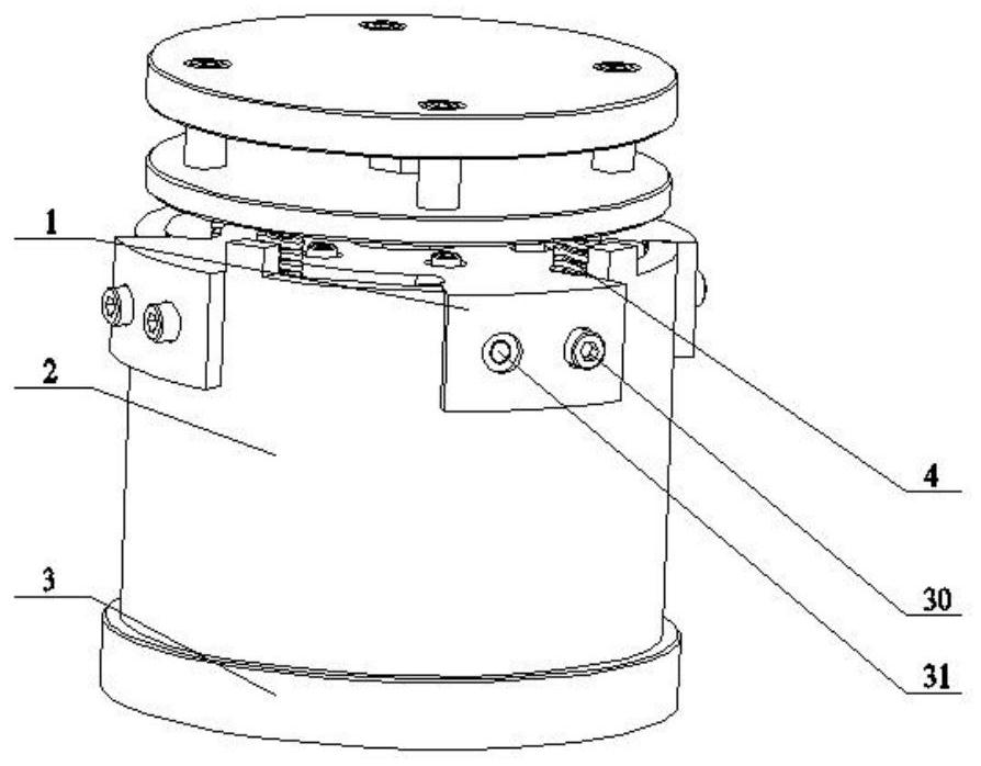
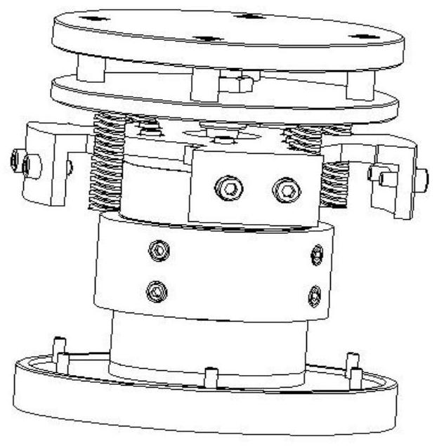
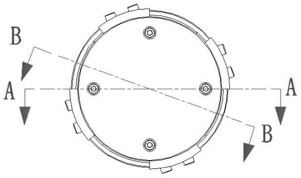
[0039] according to Figure 1 to Figure 15 As shown, the present invention provides a kind of quasi-zero stiffness electromagnetic vibration isolator suitable for ultra-low frequency vibration reduction and isolation, a kind of quasi-zero stiffness electromagnetic vibration isolator suitable for ultra-low frequency vibration reduction and isolation, which includes a stator mounting plate 1, The housing composed of the vibration isolator cover 2 and the base 3, and the mover assembly, the upper stator assembly and the lower stator assembly etc. located inside the housing. The lower stator assembly is installed on the base 3, the vibration isolator cover 2 is installed on the base 3, the stator mounting plate 1 is installed on the vibration isolator cover 2, the upper stator assembly is installed on the stator mounting plate 1, and the spring 4 is installed on the moving Between the subassembly and the vibration isolator cover 2, the movable subassembly is placed on the spring 4...


PUM


Abstract

The invention relates to a quasi-zero stiffness electromagnetic vibration isolator suitable for ultralow-frequency vibration reduction and isolation. The invention relates to the technical field of vibration control. When a vibration isolator is in a static balance position, upper and lower air gaps are equal, and the electromagnetic attraction of an upper stator assembly to a rotor assembly is equal to the electromagnetic attraction of a lower stator assembly to the rotor assembly. When the load tends to move upwards, the upper air gap is smaller than the lower air gap, the resultant force borne by the rotor assembly is upward, the upward movement trend is accelerated, the negative stiffness characteristic is shown, and a negative stiffness execution mechanism formed by the upper stator assembly, the lower stator assembly and the rotor assembly is connected with a positive stiffness spring in parallel to achieve quasi-zero stiffness. When the load tends to move downwards, the lower air gap is smaller than the upper air gap, the resultant force borne by the rotor assembly is downwards, the downward movement trend is accelerated, the negative stiffness characteristic is shown, and a negative stiffness execution mechanism formed of the upper stator assembly, the lower stator assembly and the rotor assembly is connected with the positive stiffness spring in parallel to achieve quasi-zero stiffness.

Description

technical field [0001] The invention relates to the technical field of vibration control, and is a quasi-zero-stiffness electromagnetic vibration isolator suitable for ultra-low frequency vibration reduction and isolation. Background technique [0002] As an important technology of vibration control, vibration isolation technology aims to take certain measures between the vibration source and the system, and install appropriate vibration suppression or vibration isolation equipment to isolate the direct transmission of vibration. Traditional passive vibration isolators can theoretically only be used for excitation frequencies greater than The vibration at twice the natural frequency of the system plays an attenuating role. With the continuous improvement of vibration isolation requirements, there is an urgent need for a vibration isolation technology that can maintain static support capacity and have low dynamic stiffness in a low-frequency environment. Therefore, quasi-ze...

Claims


Application Information

Patent Timeline
Patent Type & Authority Applications(China)
IPC IPC(8): F16F15/03F16F15/04F16F15/06F16F6/00
CPCF16F13/00F16F15/03H02K5/24H02K41/03H02K2213/09F16F15/046F16F2228/063H02K1/185
Inventor 靳国永袁俊杰叶天贵刘志刚
Owner HARBIN ENG UNIV
Why Eureka
Try Eureka