A real-time treatment system for laboratory organic waste liquid

A technology for real-time treatment of organic waste liquid, applied in the direction of reducing greenhouse gases, combustion types, lighting and heating equipment, etc., can solve problems such as untimely waste treatment, low waste treatment costs, leakage, etc., to increase stability and Efficiency, ensuring temperature and time, increasing the effect of the reaction process

Active Publication Date: 2022-03-08
TSINGHUA UNIV
View PDF14 Cites 0 Cited by
  • Summary
  • Abstract
  • Description
  • Claims
  • Application Information

AI Technical Summary

Problems solved by technology

[0005] Aiming at the deficiencies in the prior art of untimely waste disposal, potential safety hazards such as leakage, and high processing costs, the present invention provides an on-site real-time treatment system for laboratory organic waste liquid, which can effectively treat experimental waste on site. Chamber organic waste liquid, and make the treated organic waste liquid meet the national discharge standard, and can be discharged directly; the treatment efficiency of the organic waste liquid in the present invention is high, and the cost of waste single-volume treatment is low

Method used


Image

  • A real-time treatment system for laboratory organic waste liquid
  • A real-time treatment system for laboratory organic waste liquid
  • A real-time treatment system for laboratory organic waste liquid

Examples


Embodiment 1

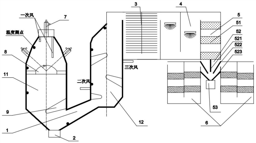
[0054] Embodiment 1 of the present invention provides an on-site real-time treatment system for laboratory organic waste liquid. The structure of the system is as follows: figure 1 shown, incl. Waste liquid reaction device 1, slag particle recovery tank 2, waste heat recovery device 3, flue gas quenching and desulfurization integrated device 4, dehydration device 5, flue gas purification device 6, waste liquid injection device 7, flame stabilizer 8 and diversion arch 9.

[0055] The waste liquid reaction device 1 includes a primary reaction body 11 and a secondary reaction body 12; a through hole is opened on the side of the primary reaction body 11 near the bottom, and communicates with the secondary reaction body 12 through an inclined upward connecting channel. The angle between the direction of the channel and the horizontal direction is 15°-45°; the bottom of the primary reaction body 11 is provided with a slag particle recovery tank 2; the interior of the primary reacti...

Embodiment 2

[0085] In embodiment two, the waste liquid reaction device 1 is as follows Figure 4 Shown structure, its difference with embodiment 1 has:

[0086] The waste liquid reaction device 1 includes a primary reaction body 11 and a secondary reaction body 12 ; the lower part of the primary reaction body 11 enters the upper part of the secondary reaction body 12 through a channel.

[0087] A divider 121 is arranged in the middle of the secondary reaction body 12 to divide the secondary reaction body 12 into a first reaction chamber and a second reaction chamber, and there is a gap between the flow divider and the bottom of the secondary reaction body 12, so that the The reactants produced by the reaction in the first reaction chamber enter the second reaction chamber through the gap. The upper part of the second reaction chamber is the end of the waste liquid reaction device 1, and the end is provided with a waste heat recovery device 3, a flue gas rapid cooling and desulfurization ...

Embodiment 3

[0089] In the third embodiment, the structure of the dehydration device 5 and the number and arrangement position of the flue gas purification device 6 are different from those in the above-mentioned embodiment. The combined structure of the dehydration device 5 and the flue gas purification device 6 is as follows Figure 5 shown.

[0090] Depend on Figure 5 It can be seen that the dehydration device 5 in the third embodiment still includes a pre-order dehydration device 51 , a terminal dehydration device 52 and a water collection tank 53 .

[0091] The pre-sequence dehydration device 51 is equipped with a multi-stage dehydration body (such as a secondary dehydration body). The dehydration body is made of polyurethane composite material. Enter the terminal dehydration device 52.

[0092] The walls of the terminal dehydration device 52 are all provided with dehydration material linings. The terminal dehydration device 52 includes a vertical baffle 521 , an inclined baffle 5...


PUM


Abstract

The invention provides an on-site real-time treatment system for laboratory organic waste liquid, wherein the waste liquid reaction device (1) includes a primary reactant (11) and a secondary reactant (12) communicated through channels; the primary reactant ( 11) It is olive-shaped, with a flame stabilizer (8) inside and primary air and waste liquid; the secondary reaction body (12) is in the shape of a straight cylinder with eccentric necking, the left side of the top is a slope and the right side is a vertical surface, and the top The outlet section is about 1 / 2-2 / 3 of the middle section; the reactant of the waste liquid reaction device (1) is cooled by the waste heat recovery device (3), quenched and desulfurized by the flue gas quenching and desulfurization integrated device (4), and dehydrated The device (5) removes moisture, and finally the harmful components are filtered out by the flue gas purification device (6). The first-stage reaction body can guarantee the reaction space of the waste liquid; the second-stage reaction body can ensure the waste liquid treatment temperature; the invention is beneficial to the staged treatment of the waste liquid, increases the reaction process of the reactants, and ensures the reaction temperature, space and time of the waste liquid.

Description

technical field [0001] The invention belongs to the technical field of organic waste liquid experimental equipment, and relates to an on-site real-time treatment system for laboratory organic waste liquid. Background technique [0002] With the rapid development of science and technology in our country, the laboratories of universities, scientific research institutions and enterprises have been continuously expanded, and the types, quantity and scale of laboratories have also continued to grow, followed by pollution problems caused by laboratories. Laboratory pollutants mainly include: solid waste, waste liquid, exhaust gas, noise and vibration, electromagnetic radiation, and biological pollutants of viruses and pathogenic bacteria. University laboratory waste is highly toxic and harmful, but the environmental protection department has not included it in the environmental protection testing items. Even if it is included, it is difficult to detect because of its small amount ...

Claims


Application Information

Patent Timeline
Patent Type & Authority Patents(China)
IPC IPC(8): F23G7/04F23G5/027F23G5/44F23G5/46F23J15/00F23J15/02F23J15/06
CPCF23G7/04F23G5/027F23G5/44F23G5/446F23G5/46F23J15/006F23J15/02F23J15/025F23J15/06F23G2201/30F23G2202/101F23G2202/103Y02E20/30
Inventor 禚玉群
Owner TSINGHUA UNIV
Why Eureka
Try Eureka