Fully distributed pipeline erosion monitoring system and method based on optical fiber sensing

A fully distributed, optical fiber sensing technology, applied in measuring devices, measuring heat, using optical devices, etc., can solve problems such as difficulty in identifying the thinning of the protective layer of the pipeline covering soil, difficult to achieve full coverage monitoring, and accuracy impact. Achieve the effect of low cost, easy installation and convenient maintenance

Active Publication Date: 2021-04-23
南京嘉兆仪器设备有限公司
View PDF7 Cites 1 Cited by
  • Summary
  • Abstract
  • Description
  • Claims
  • Application Information

AI Technical Summary

Problems solved by technology

[0003] At present, in terms of monitoring the thickness of the covering soil layer on the surface of the pipeline, the industry mainly adopts the method of manual inspection and the use of sand markers in important areas. have a certain time lag
Among them, manual inspection often requires the pipeline to be partially exposed in a certain area before discovering the problem, and it is difficult to identify the thinning of the pipeline covering soil protection layer
However, for some emerging instrument measurement methods based on the principle of optics and acoustics, they are easily restricted by factors such as weather and climate, which greatly affects their accuracy.

Method used


Image

  • Fully distributed pipeline erosion monitoring system and method based on optical fiber sensing
  • Fully distributed pipeline erosion monitoring system and method based on optical fiber sensing
  • Fully distributed pipeline erosion monitoring system and method based on optical fiber sensing

Examples


Embodiment

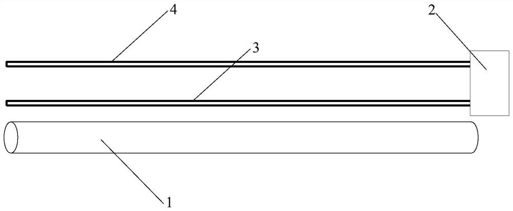
[0034] Embodiment: In this embodiment, the soil in which the pipeline 1 and the two temperature sensing optical cables are buried is clay.

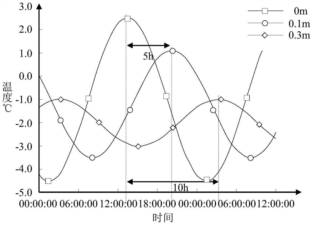
[0035] like image 3 As shown, the three soil depths from the ground in the same vertical direction are set to be 0m, 0.1m and 0.3m, and the temperature-time curves of the three soils at 0m, 0.1m and 0.3m all show periodicity The law of change. Compared with the temperature-time curve at the burial depth of 0m, the phase differences between the 0.1m and 0.3m curves are 5 and 10h respectively, that is, the difference in burial depth is different, and the phase difference is also different. Therefore, by burying the temperature sensing optical cable at the pipeline 1 to be tested and the temperature sensing optical cable at the reference point above, the erosion of the soil on the surface of the pipeline 1 can be judged by the change of the phase difference of the two temperature-time curves. And because the external heat source changes c...


PUM


Abstract

The invention discloses a fully distributed pipeline erosion monitoring system and method based on optical fiber sensing, and the system comprises a pipeline, two temperature sensing optical cables, and a temperature demodulator, the pipeline is buried in a soil body, the first temperature sensing optical cable is laid in the soil body 10-20cm away from the upper part of the pipeline, and a second temperature sensing optical cable is laid at a certain distance right above the first temperature optical cable; the two temperature sensing optical cables are laid in the whole axial direction of the pipeline, and the same ends of the two temperature sensors are connected with the temperature demodulator to form a loop; and the temperature demodulator collects the temperature of a soil body at the buried position through the temperature sensing optical cables, the first temperature sensing optical cable measures the temperature T1 at the pipeline, and the second temperature sensing optical cable measures the temperature T2 at the reference position. The system has the characteristics of simple installation, immediate feedback, labor saving and good weather interference resistance.

Description

technical field [0001] The invention belongs to geological monitoring technology, in particular to a fully distributed pipeline erosion monitoring system and method based on optical fiber sensing. Background technique [0002] In pipeline engineering, the exposure of the pipeline due to the thinning of the covering soil layer will make its integrity more likely to be threatened, especially when the pipeline passes through high-consequence areas, the leakage will have a serious impact on the local natural ecology and public health. Therefore, the prevention and monitoring of pipeline erosion is the focus of pipeline operation. [0003] At present, in terms of monitoring the thickness of the covering soil layer on the surface of the pipeline, the industry mainly adopts the method of manual inspection and the use of sand markers in important areas. have a certain time lag. Among them, manual inspection often requires that the pipeline is partially exposed in a certain area to...

Claims


Application Information

Patent Timeline
IPC IPC(8): G01K11/32G01B11/06
Inventor 杨宇烨邵翰林史波
Owner 南京嘉兆仪器设备有限公司
Why Eureka
Try Eureka