
Pulse type liquid-solid two-phase flow erosive wear test device in airflow jet environment

An air jet and wear test technology, applied in the direction of measuring devices, wear resistance testing, instruments, etc., can solve the problems of high cost, large research and development costs, and the inability to realize high-speed liquid-solid two-phase flow erosion, etc., to achieve responsiveness, The effect of simple structure

Pending Publication Date: 2021-04-23
宁波市产品食品质量检验研究院(宁波市纤维检验所)
View PDF0 Cites 0 Cited by
  • Summary
  • Abstract
  • Description
  • Claims
  • Application Information

AI Technical Summary

Problems solved by technology

[0003] The erosion and wear mechanism and law of high-speed liquid-solid two-phase flow in the air jet environment are extremely complex, and there is currently no suitable test device that can be used to study the erosion and wear mechanism and law in this working condition
Among the existing test devices close to the liquid-solid two-phase flow conditions in the air jet environment, the continuous high-temperature and high-speed gas-solid two-phase flow erosion wear test device has a complex equipment structure, very high cost and large energy consumption during the test process; The liquid erosion rate of the rotary erosion wear test device is too low to achieve high-speed liquid-solid two-phase flow erosion; the aforementioned two test devices cannot well restore the pulsed liquid-solid two-phase flow in the air jet environment. Erosion conditions, if you want to realize the erosion test under this condition, theoretically, you need to invest a lot of research and development costs

Method used


Image

  • Pulse type liquid-solid two-phase flow erosive wear test device in airflow jet environment
  • Pulse type liquid-solid two-phase flow erosive wear test device in airflow jet environment

Examples


Embodiment

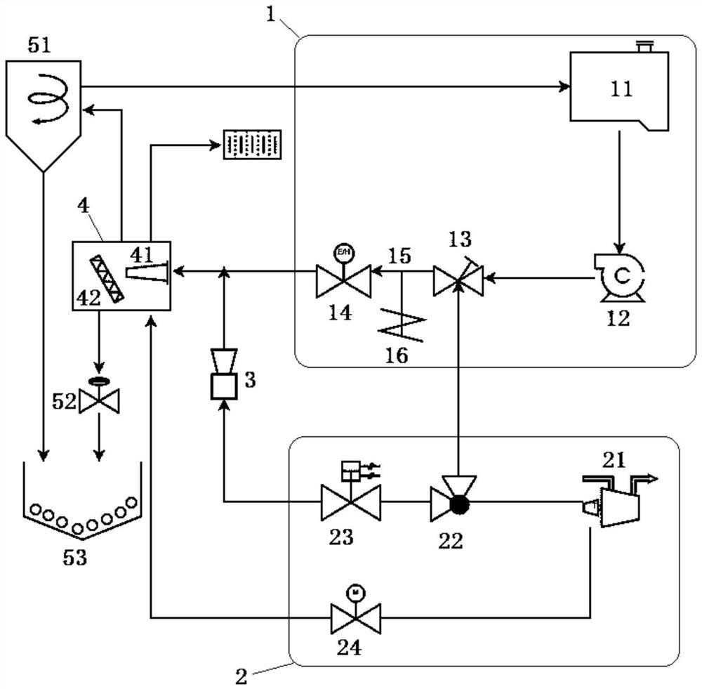
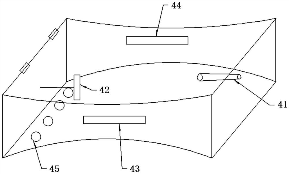
[0023] Example: A pulsed liquid-solid two-phase flow erosion wear test device in an air jet environment, the structure is as follows figure 1 and figure 2 As shown, it includes a water supply module 1, an air supply module 2, a particle loading device 3 and an erosion test chamber 4; the water supply module 1 provides a high-speed liquid flow for the erosion and wear test, and includes a water tank 11, a centrifugal pump 12, Pneumatic angle seat valve 13 and throttle valve 14, the pneumatic angle seat valve 13 forms a pressure wave at the outlet using the water hammer phenomenon formed when it is closed, and the pressure wave is transmitted to the throttle valve 14 to form a high-speed liquid flow, so The outlet of the throttle valve 14 is connected with the erosion test chamber 4; the air supply module 2 provides an air source for the pneumatic angle seat valve 13, the erosion test chamber 4, and the particle loading device 3, respectively making the pneumatic angle seat Th...


PUM


Abstract

The invention discloses a pulse type liquid-solid two-phase flow erosive wear test device in an airflow injection environment. The pulse type liquid-solid two-phase flow erosive wear test device comprises a water supply module, an air supply module, a particle loading device and an erosion test box. The water supply module provides high-speed liquid flow for an erosive wear test and comprises a water tank, a centrifugal pump, a pneumatic angle seat valve and a throttle valve which are connected in sequence, and the pneumatic angle seat valve transmits a water hammer phenomenon formed during closing to the throttle valve to form the high-speed liquid flow. The air supply module provides an air source for the pneumatic angle seat valve, the erosion test box and the particle loading device, enables the pneumatic angle seat valve to complete opening and closing actions respectively, drives the particle loading device to load particles to an outlet of the throttle valve and mix the particles with high-speed liquid flow, and jets airflow into the erosion test box. The pulse type liquid-solid two-phase flow erosive wear test device is simple in structure, the testing condition of water hammer pulse type liquid-solid two-phase flow erosive wear under the condition of low investment cost is achieved, and the airflow spraying speed can be continuously adjusted.

Description

technical field [0001] The invention relates to a liquid-solid two-phase flow erosion wear test device, in particular to a pulsed liquid-solid two-phase flow erosion wear test device in an air jet environment. Background technique [0002] In the industrial production environment, such as petroleum refining, coal processing, metallurgy, electric power and many other working conditions, multiphase flow of gas, liquid and solid with different components generally exists, and multiphase flow will cause impellers, engines, pumps, valves, pipelines The erosion and wear of many equipment such as nozzles and nozzles or their parts will not only shorten the service life of the equipment, but also affect the overall stability of the equipment system, which is an important hidden danger for safe production. Aiming at the mechanism and law of fluid erosion wear, there have been a large number of theoretical studies and a large number of experimental studies based on various erosion wea...

Claims


Application Information

Patent Timeline
Patent Type & Authority Applications(China)
IPC IPC(8): G01N3/56
CPCG01N3/567G01N3/565
Inventor 郑智剑王洋定贺梁鲍建辉钱咪钱正郭一萍
Owner 宁波市产品食品质量检验研究院(宁波市纤维检验所)
Learn More