

Experimental method for radar target angle measurement
A technology of target angle and experimental method, which is applied in the field of radar target measurement, can solve problems such as large error, low reliability, and cumbersome process, and achieve the effect of reducing angle measurement error and ensuring accuracy
- Summary
- Abstract
- Description
- Claims
- Application Information
AI Technical Summary
Problems solved by technology
Method used
Image

Examples
Embodiment 1
[0043] Embodiment 1: Stationary target.
[0044] combined with Figure 1 to Figure 2 To specifically describe this embodiment:
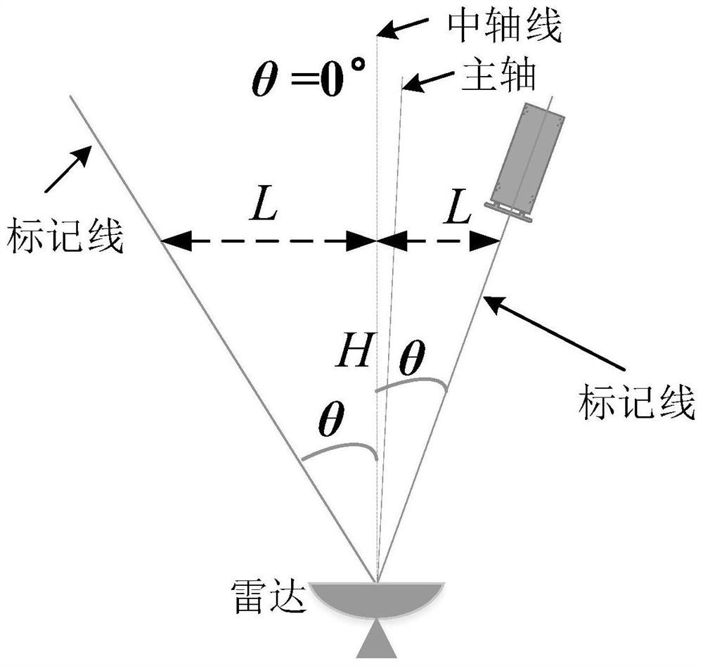
[0045]Step 1. Build an experimental system for radar to measure target angle. First set up the radar, determine the central axis of the measurement system, take H=5 meters, and determine the offset L of different angles (±9°, ±7°, ±5°, ±3°) according to the relational expression L=H tanθ , connect the radar projection on the ground and the offset point, and draw a marker line, see figure 1 .
[0046] Step 2. Radar antenna pointing calibration. Place the calibration body on the central axis of the angle measurement system, constantly adjust the antenna pointing and measure the angle of the calibration body, so that the angle of the calibration body is smaller than the threshold δ (δ = 1°), and the angle of the calibration body is recorded as θ T .
[0047] Step 3, place the target on the marking line of multiple angles (±9°, ±7°, ±5°, ±3°) withi...
Embodiment 2
[0049] Embodiment 2: sports target.
Embodiment approach
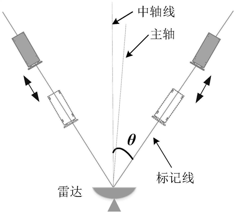
[0051] Step 1. Set up the radar, determine the main axis, select the first line near the main axis, that is, the central axis, and draw marking lines at different angles (-6°, ±3°) on the ground.
[0052] Step 2. Radar antenna pointing calibration. If the test environment or test conditions have not changed, there is no need to recalibrate the radar antenna pointing. Set the threshold δ=1°.
[0053] Step 3. Place the target on the marking line at a certain angle (-6°, -3°, +3°) within the range of the radar beam, and reciprocate the motion platform along the marking line, and use the radar to measure the angle of the target. The schematic diagram of the test is shown in 3.
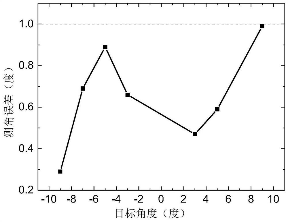
[0054] Step 4. Subtract the antenna main axis pointing angle θ from a set of angle data measured for each angle T , and then averaged, and then subtracted from the actual angle to obtain the angle measurement error. Measurement results such as Figure 4 shown.
[0055] We counted the test results of ...
PUM
 Abstract
Description
Claims
Application Information