
Base with metal circuit, voice coil motor and manufacturing method

A technology of metal circuit and base, which is applied to the parts of color TV, parts of TV system, printed circuit assembled with electrical components, etc. It can solve the problem of increasing the overall thickness of the voice coil drive motor, increasing the cost, and the manufacturing of flexible circuit boards. Solve problems such as high technology and cost, and achieve the effect of meeting diversified layout requirements, increasing layout density, and expanding layout space

Active Publication Date: 2021-04-23
SUZHOU GYZ ELECTRONICS TECH CO LTD
View PDF17 Cites 5 Cited by
  • Summary
  • Abstract
  • Description
  • Claims
  • Application Information

AI Technical Summary

Problems solved by technology

At present, in the existing technology, the way to deal with this technical problem mostly needs to adopt the method of flexible circuit, and complete the space overlap of the circuit in the middle extension section, but the manufacturing process and cost of the flexible circuit board are relatively compared with the metal circuit formed by traditional stamping. branch is relatively higher
Therefore, the use of flexible circuits is not conducive to efficient manufacturing and promotion, and will also cause the overall manufacturing cost of the drive motor to remain high
Another way is to make a double-layer circuit board, but the double-layer circuit board needs two times of stamping and bending, which will also increase the cost to a certain extent, and the double-layer circuit will also increase the overall thickness of the voice coil drive motor , which is not conducive to the miniaturization of the overall size of the voice coil drive motor

Method used


Image

  • Base with metal circuit, voice coil motor and manufacturing method
  • Base with metal circuit, voice coil motor and manufacturing method
  • Base with metal circuit, voice coil motor and manufacturing method

Examples


Embodiment Construction

[0044] In the description of the present invention, it should be noted that the orientation or positional relationship indicated by the terms "upper", "lower", "inner", "outer" and the like are based on the orientation or positional relationship shown in the accompanying drawings, and are only for It is convenient to describe the present invention and simplify the description, but does not indicate or imply that the device or component referred to must have a specific orientation, be constructed and operate in a specific orientation, and thus should not be construed as limiting the present invention.

[0045] In the description of the present invention, it should be noted that, unless otherwise clearly specified and limited, the term "connection" should be understood in a broad sense, and those of ordinary skill in the art can understand the above terms in the present invention in specific circumstances. specific meaning.

[0046] Below, will combine Figure 1 to Figure 14 Th...


PUM


Abstract

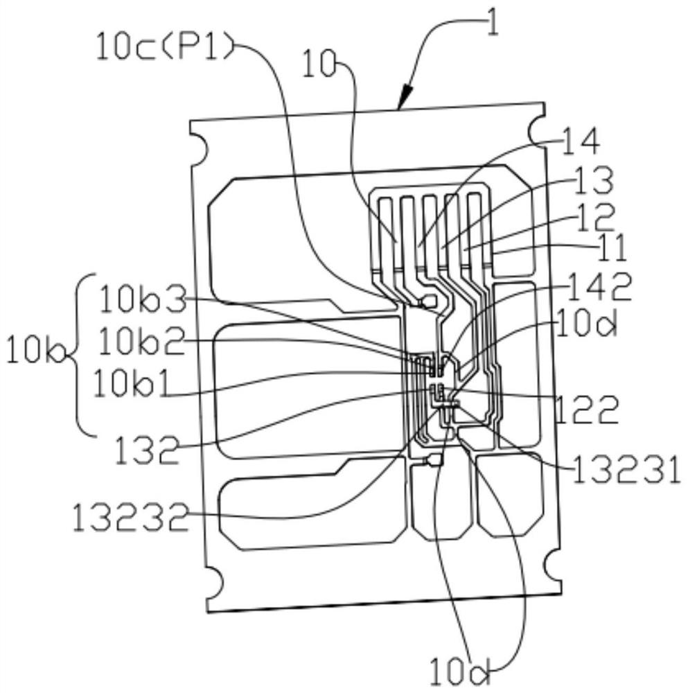
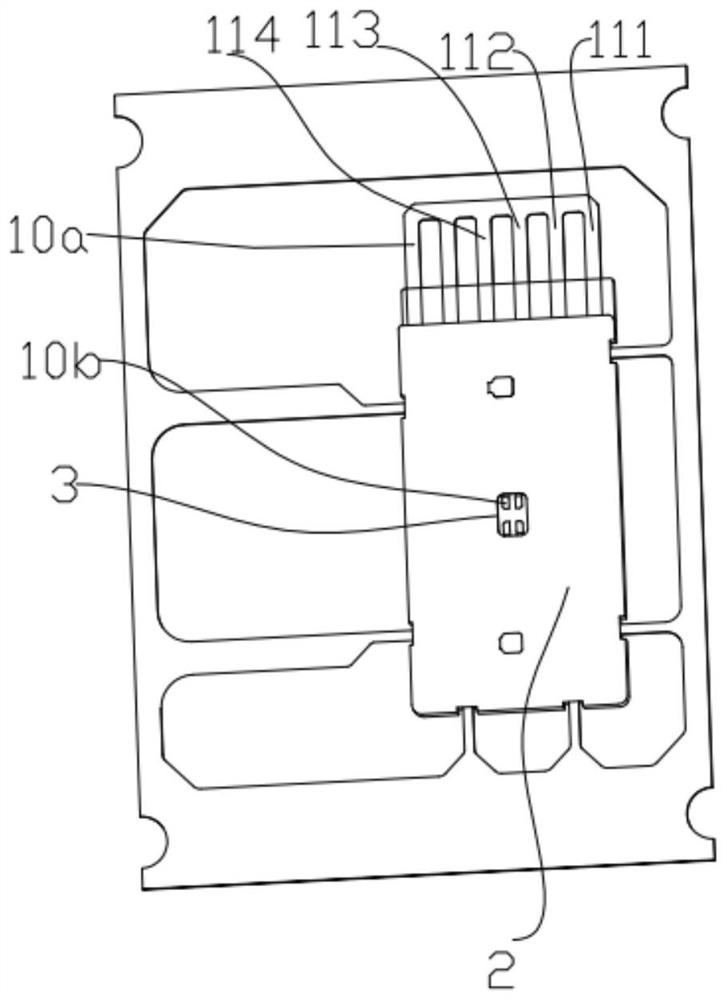
The invention relates to a base with a metal circuit. The base comprises an electronic element, a metal circuit welded with the electronic element and formed by one-step stamping, and a plastic body integrally injection-molded with the metal circuit, wherein the metal circuit at least comprises three branches, each branch comprises pins, weld legs and a main body part, one ends of the pins are arranged in parallel and at intervals, the other ends of the weld legs are arranged corresponding to pins of the electronic element one by one, the main body part is connected with the pins and the weld legs, the arrangement sequence of the first pins, the second pins and the third pins is different from that of the first welding pins, the second welding pins and the third welding pins. the weld legs of one branch is bent towards the other weld legs of the other branches and partially overlaps with the projection of the other weld legs in at least one of the vertical direction and the horizontal direction. According to the base , one weld leg of the metal circuit is bent to realize space crossing and realize space overlapping with the other welding pin, so that the arrangement density of the metal circuit is increased.

Description

technical field [0001] The invention relates to the technical field of metal circuits, in particular to a base with a metal circuit, a voice coil motor and a manufacturing method. Background technique [0002] Existing bases and voice coil motors with metal circuits, such as the patent application with publication number CN108989511A, this type of base includes electronic components, metal circuits, first plastic parts and second plastic parts, metal circuits and the electronic The components are connected, and include a plurality of branches, and the branches are connected to the pins of the electronic components in a one-to-one correspondence; the first plastic part is located at the position where the metal circuit is connected to the electronic component, and the metal circuit is connected to the electronic component. All branches of the circuit are connected as one. Another patent application with the publication number CN110703536A discloses a driving mechanism, which...

Claims


Application Information

Patent Timeline
Patent Type & Authority Applications(China)
IPC IPC(8): H05K1/18H05K3/34H04N5/225
Inventor 耿叶贝子
Owner SUZHOU GYZ ELECTRONICS TECH CO LTD
Learn More