Secondary ejection die casting die

A die-casting mold and secondary ejection technology, applied in the field of die-casting molds, can solve the problems of reducing the force of ejection, reducing the quality of die-casting products, reducing flexibility, etc., so as to enhance the force of ejection and enhance the effect of ejection , the effect of expanding the scope of application

Active Publication Date: 2021-04-27
宝鑫(宁波)模具科技有限公司
View PDF13 Cites 2 Cited by
  • Summary
  • Abstract
  • Description
  • Claims
  • Application Information

AI Technical Summary

Problems solved by technology

[0003] However, the existing secondary ejection die-casting molds have great defects when they are reused. The ejector parts of the existing secondary ejection die-casting molds cannot be disassembled, which is inconvenient for later maintenance and shortens the service life of the die-casting molds , is not conducive to cleaning after use, increases the impurities in the mold, reduces the quality of die-casting products, cannot be installed according to needs, and reduces the flexibility of use. The ejection parts of the existing secondary ejection die-casting mold cannot be lifted Adjustment is not conducive to expanding the application range of the product and weakening the effect of ejection. In view of the tight fit between the die-casting product and the mold, it cannot provide good ejection support and reduces the strength of ejection. When the length of the ejected part is insufficient during the mold release process, the length of the ejected part cannot be supplemented

Method used


Image

  • Secondary ejection die casting die
  • Secondary ejection die casting die
  • Secondary ejection die casting die

Examples


Embodiment Construction

[0023] In order to make the technical means, creative features, goals and effects achieved by the present invention easy to understand, the present invention will be further described below in conjunction with specific embodiments.

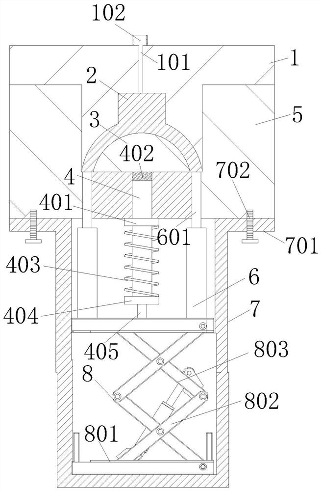
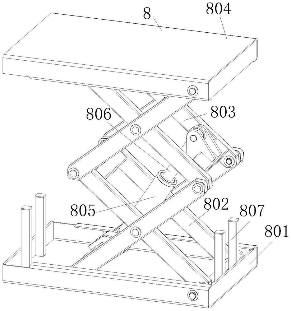
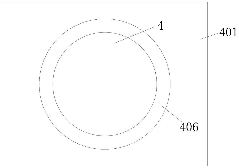
[0024] Such as Figure 1-Figure 3 As shown, a secondary ejection die-casting mold according to the present invention includes a fixed module 1, a movable mold assembly 5, a first hydraulic cylinder 4, an installation frame 7, and a lifting assembly 8, and the center of the top of the fixed module 1 is provided with a filling Liquid channel 101, liquid filling port 102 is provided on the upper side of liquid filling channel 101, movable mold assembly 5 is arranged on the bottom of fixed module 1, and core 3 is arranged on the upper part of movable mold assembly 5, and the gap between core 3 and fixed module 1 There is a die-casting part 2 between them, the first hydraulic cylinder 4 is slidably fitted in the movable mold assembly 5, the installatio...


PUM


Abstract

The invention relates to the technical field of die casting dies, in particular to a secondary ejection die casting die. The secondary ejection die casting die comprises a fixed die block, a movable die assembly, a first hydraulic cylinder, a mounting frame and a lifting assembly. The first hydraulic cylinder drives a first hydraulic rod, the top end of the first hydraulic rod is fixed to a supporting table, the first hydraulic cylinder pushes a die core upwards to move upwards, the first hydraulic cylinder drives the first hydraulic rod and a second hydraulic cylinder to synchronously drive a second hydraulic rod, a die casting and the die core synchronously move upwards, first-time ejection and separation of the die casting and the die core from the movable die assembly are achieved, when a sliding plate is tightly attached to the bottom end of the movable die assembly, a spring starts to be compressed, a baffle at the bottom end of the spring reduces the upward speed of the first hydraulic cylinder, the upward moving speed of the die casting is larger than that of the die core, secondary ejection is achieved, the die casting is separated from the die core, and therefore damage to the die casting due to one-time ejection of the die casting and over-tight die core is avoided, the stability of the die casting is ensured, and the quality of die-cast products is improved.

Description

technical field [0001] The invention relates to the technical field of die casting molds, in particular to a secondary ejection die casting mold. Background technique [0002] When the finished product produced by die-casting is taken out from the mold, it is necessary to use an ejection mechanism to eject the finished product. The ejection action is generally completed at one time, but when the die-casting product has a special shape or cannot be ejected at one time due to other reasons, it is necessary A secondary ejection die-casting mold is needed. The secondary ejection die-casting mold can make the die-casting finished product be taken out of the mold more smoothly, and reduce the damage to the product caused by the excessive force of the primary ejection. [0003] However, the existing secondary ejection die-casting mold has great defects when it is reused. The ejection parts of the existing secondary ejection die-casting mold cannot be disassembled, which is not conv...

Claims


Application Information

Patent Timeline
IPC IPC(8): B22D17/22
CPCB22D17/2236
Inventor 郑志强夏鹏
Owner 宝鑫(宁波)模具科技有限公司
Why Eureka
Try Eureka