Construction method for top plate of sealed space at top of immersed tube

A technology of sealing space and construction method, applied in the direction of manufacturing tools, supply devices, ceramic molding machines, etc., can solve the problems of increasing the construction time of the immersed pipe roof, unable to reuse the scaffolding, and increasing the construction cost, so as to shorten the construction time and reduce the Construction cost and material saving effect

Active Publication Date: 2021-04-27
CCCC FOURTH HARBOR ENG CO LTD
View PDF9 Cites 0 Cited by
  • Summary
  • Abstract
  • Description
  • Claims
  • Application Information

AI Technical Summary

Problems solved by technology

[0004] The purpose of the present invention is: when the formwork of upper roof 1 is erected by scaffolding in the prior art, after the upper roof 1 is poured, the scaffolding cannot be taken out from the grid space 3, so the scaffolding of this method cannot be reused and wastes materials , Moreover, it takes a long time to set up the scaffolding, which increases the construction time of the immersed tube roof and increases the construction cost. A construction method for the roof of the sealed space at the top of the immersed tube is provided

Method used


Image

  • Construction method for top plate of sealed space at top of immersed tube
  • Construction method for top plate of sealed space at top of immersed tube
  • Construction method for top plate of sealed space at top of immersed tube

Examples


Embodiment 1

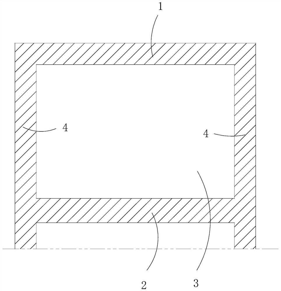
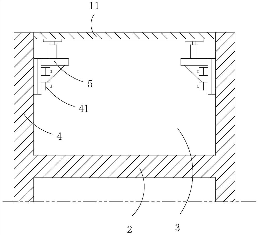
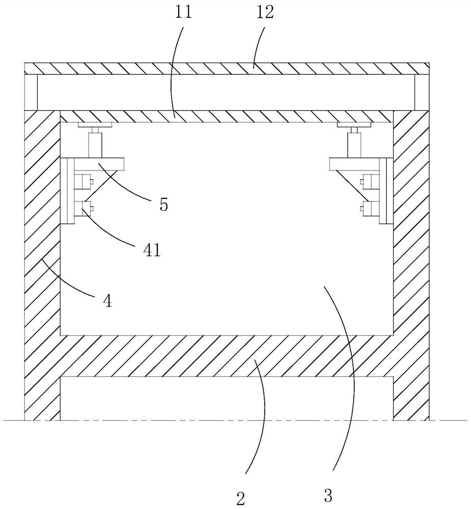
[0039] like Figure 2-4 As shown, a construction method for the roof of the sealed space at the top of the immersed tube includes the following steps:

[0040] S1. Concrete the side wall 4, and pre-embed the connector 41 on the side wall 4, the connector 41 is located at the top of the side wall 4;

[0041] S2. Make a support structure 5, and connect the support structure 5 with the connector 41, so that the support structure 5 is located in the grid space 3;

[0042] S3. Construct the bottom form 11 for pouring the upper roof 1 on the support structure 5, and use the support structure 5 to support the bottom form 11;

[0043] S4. Construct top form 12 above described bottom form 11, form the pouring space that is used for described upper strata roof 1 molding between described bottom form 11 and described top form 12;

[0044] S5. Pouring and forming the upper roof 1 .

[0045] In the above solution, the support structure 5 is detachably connected to the connecting member ...

Embodiment 2

[0050] like Figure 5 and 6As shown, in the construction method for the roof of the sealed space at the top of the immersed tube described in this embodiment, the middle part of the entire bottom form 11 is in a suspended state, so the gravity bending moment on the bottom form 11 increases continuously from the middle to both ends , so the solution of this embodiment differs from that of Embodiment 1 in that: the bottom mold 11 includes a support plate 13 arranged horizontally, the bottom of the support plate 13 is provided with an arched part 14, and the arched part 14 One end is connected to one of the support structures 5 , the other end is connected to the support structure 5 on the opposite side wall 4 , and the arched component 14 is connected to the support plate 13 by support.

[0051] On the basis of the above, in a further preferred manner, the arched part 14 is a space truss structure, so that under the same strength, the structural quality of the arched part 14 ca...

Embodiment 3

[0054] like Figure 4 and 6 As shown, a construction method for the roof of the sealed space at the top of the immersed tube described in this embodiment is different from Embodiment 1 or 2 in that: the support structure 5 includes a base 51, and the base 51 is set There is a lifting mechanism 52, and the top of the lifting mechanism 52 is connected with a support platform 53 for supporting the bottom mold 11;

[0055] The step S3. constructing the bottom form 11 for pouring the upper roof 1 on the support structure 5, and using the support structure 5 to support the bottom form 11, specifically:

[0056] S31. Constructing the bottom form 11 for pouring the upper roof 1 on the support structure 5;

[0057] S32. placing the bottom mold 11 on the support table 53;

[0058] S33. Adjust the lifting mechanism 52 to make the bottom mold 11 reach a predetermined height.

[0059] The beneficial effects of this embodiment: use the lifting mechanism 52 to adjust the position height ...


PUM


Abstract

The invention relates to the field of immersed tubes, in particular to a construction method for a top plate of a sealed space at the top of an immersed tube. The construction method comprises the following steps: S1, a side wall is poured, and a connecting piece is pre-buried on the side wall, wherein the connecting piece is positioned at the upper part of the side wall; S2, a supporting structure is manufactured, and the supporting structure is connected with the connecting piece, so that the supporting structure is located in a grillwork space; S3, a bottom die used for pouring the upper-layer top plate is constructed on the supporting structure, and the bottom die is supported on the supporting structure; S4, a top die is constructed above the bottom die, so that a pouring space used for forming the upper-layer top plate is formed between the bottom die and the top die; and S5, an upper-layer top plate is formed through pouring. According to the construction method, used materials, manufacturing and mounting cost and time cost are far lower than those of erecting a scaffold, and therefore the materials are saved, corresponding construction time is shortened, and the construction cost is reduced.

Description

technical field [0001] The invention relates to the field of immersed tubes, in particular to a construction method for the roof of the sealed space at the top of the immersed tube. Background technique [0002] like figure 1 As shown, when prefabricating the immersed tube structure, in some parts, in order to reduce the gravity load on the upper part of the immersed tube, its strength needs to meet the requirements of use, and waterproof requirements must also be taken into account. Therefore, it is necessary to prefabricate the immersed tube roof with at least two layers grid structure, and there will be a grid space 3 between the upper roof 1 and the lower roof 2, the side walls around the grid space 3 and the upper roof 1 and the lower roof 2 are mutually sealed, so that the grid space 3 Form a sealed space. [0003] For the construction of the above-mentioned upper roof 1, due to the large height difference between the upper roof 1 and the lower roof 2, generally afte...

Claims


Application Information

Patent Timeline
Patent Type & Authority Applications(China)
IPC IPC(8): B28B13/02B28B23/02
CPCB28B23/02B28B23/024B28B13/02
Inventor 石志鹏邹正周张涛朱成欧伟山刘轩源陈伟龙陈厚张雅辉肖桂森
Owner CCCC FOURTH HARBOR ENG CO LTD
Why Eureka
Try Eureka