Needle valve type hot runner system

A needle-valve hot runner and valve needle technology, which is applied in the field of hot runner system, can solve the problems of affecting fluid outflow, valve needle vibration, driving force and pressure maintenance are not very stable, etc.

Pending Publication Date: 2021-04-27
来诺精密热流道科技(苏州)有限公司
View PDF0 Cites 0 Cited by
  • Summary
  • Abstract
  • Description
  • Claims
  • Application Information

AI Technical Summary

Problems solved by technology

[0003] The needle valve hot runner system drives the movement of the valve needle through pneumatic components to control the flow of plastic fluid; in the prior art, the flow channels in the system are all diverted at the splitter plate, and then enter the valve needle hole , and because the valve needle is generally relatively long, in order to obtain a better fluid flow effect, the processing requirements for the valve needle, valve needle hole and other parts are very high, and the longer valve needle will inevitably vibrate during use The situation that affects the outflow of fluid
[0004] In addition, the valve needle of the needle valve hot runner system is driven by compressed air. In the prior art, the design of the driving mechanism for driving the valve needle refers to the cylinder, and the pressure maintaining of the driving force is not very stable; The telescopic stroke requirements of the valve needle are different, that is, each hot runner system has different requirements for the movement stroke of the drive mechanism, and the drive mechanism cannot achieve a modular design with a unified structure

Method used


Image

  • Needle valve type hot runner system
  • Needle valve type hot runner system
  • Needle valve type hot runner system

Examples


Embodiment

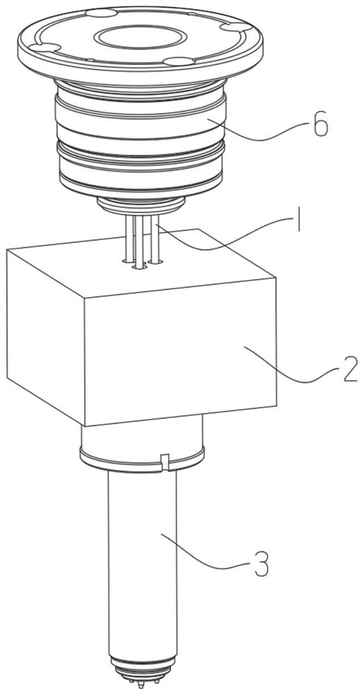
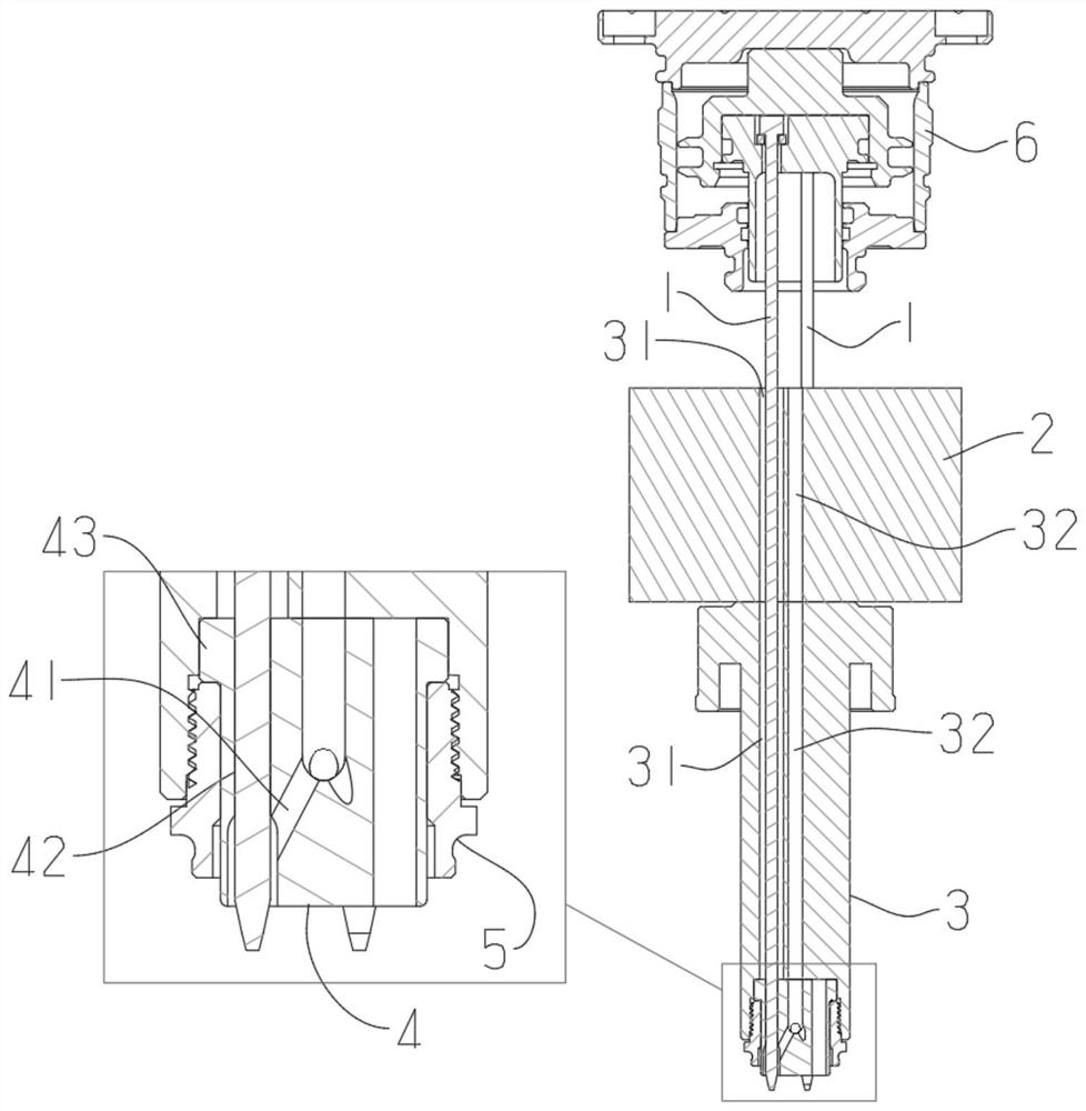
[0040] A valve needle hot runner system, such as Figure 1 to Figure 4 As shown: the hot runner system includes valve needle 1, manifold 2 and hot nozzle assembly 3;

[0041] The diverter plate is arranged at one end of the thermal nozzle assembly, the other end of the thermal nozzle assembly is the discharge end, and the diverter plate and the thermal nozzle assembly have a valve needle hole 31 communicating with each other. The valve needle is passed through the valve needle hole, and the valve needle can reciprocate along its axial direction;

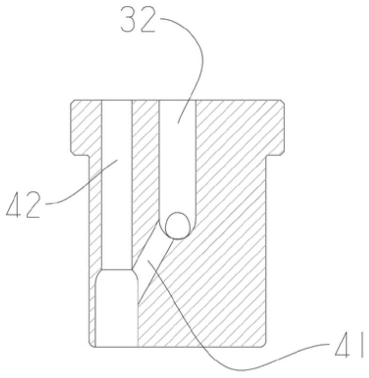
[0042] The splitter plate and the thermal nozzle assembly have a main channel 32 communicating with each other, and the discharge end of the thermal nozzle assembly is provided with a valve needle cover 4, and the valve needle cover has a branch channel communicated with the main channel. 41, and has a positioning hole 42 communicated with the valve pin hole, the shunt channel communicates with the positioning hole, the valve pin pa...


PUM


Abstract

The invention discloses a needle valve type hot runner system. The needle valve type hot runner system involves valve needles, a splitter plate, a hot nozzle assembly and a driving mechanism for driving the valve needles to stretch, wherein the splitter plate is arranged at one end of the hot nozzle assembly, the other end of the hot nozzle assembly is a discharging end, the splitter plate and the hot nozzle assembly are provided with communicating valve needle holes, the valve needles are arranged inside the valve needle holes in a penetrating mode, a movable block is arranged inside a shell body of the driving mechanism, a circle of protruding edge is arranged on the outer side wall of the movable block, the protruding edge divides a cavity into a first cavity and a second cavity, and one end of the movable block is detachably connected with a limiting block. According to the system, the stability of the valve needles can be effectively improved, and a diverting channel is arranged at the end parts of the valve needles so that the problems of temperature loss and unsmooth flow caused by too early diverting of fluids can be reduced; the stability of air pressure driving can be guaranteed through the structure of the protruding edge; and the limiting block is designed in a modular mode, and limiting blocks of different sizes can be replaced in use.

Description

technical field [0001] The invention belongs to the technical field of moulds, in particular to a hot runner system. Background technique [0002] The hot runner system is generally used in injection molds. The plastic in the runner and gate is kept in a molten state by heating. The hot runner system is generally composed of hot nozzles, manifolds, temperature control boxes and accessories. Hot nozzles are generally There are two types: open hot nozzle and needle valve hot nozzle. Since the form of hot nozzle directly determines the selection of hot runner system and the manufacture of molds, the hot runner system is often divided into open hot runner system and needle valve hot runner. system; [0003] The needle valve hot runner system drives the movement of the valve needle through pneumatic components to control the flow of plastic fluid; in the prior art, the flow channels in the system are all diverted at the splitter plate, and then enter the valve needle hole , and...

Claims


Application Information

Patent Timeline
Patent Type & Authority Applications(China)
IPC IPC(8): B29C45/28
CPCB29C45/2806B29C45/281
Inventor 郭敏敏
Owner 来诺精密热流道科技(苏州)有限公司
Why Eureka
Try Eureka