
A crane end beam transport workbench

A crane and workbench technology, applied in conveyors, conveyor objects, transportation and packaging, etc., can solve the problems of easy slippage, unfavorable end beam guidance of different specifications, poor end beam guidance applicability, etc., and achieve good conveying effect. , Good applicability, easy to move

Inactive Publication Date: 2021-06-01
烟台市特种设备检验研究院
View PDF10 Cites 0 Cited by
  • Summary
  • Abstract
  • Description
  • Claims
  • Application Information

AI Technical Summary

Problems solved by technology

However, there are some problems in the existing end beam conveying workbench: 1. In the prior art, only the friction force between the support roller and the end beam is used for conveying, which is prone to slipping; The applicability of the guide is poor, which is not conducive to guiding the end beams of different specifications; 3. The existing transportation and delivery workbench is inconvenient to move, which is not conducive to transfer

Method used


Image

  • A crane end beam transport workbench
  • A crane end beam transport workbench
  • A crane end beam transport workbench

Examples


Embodiment

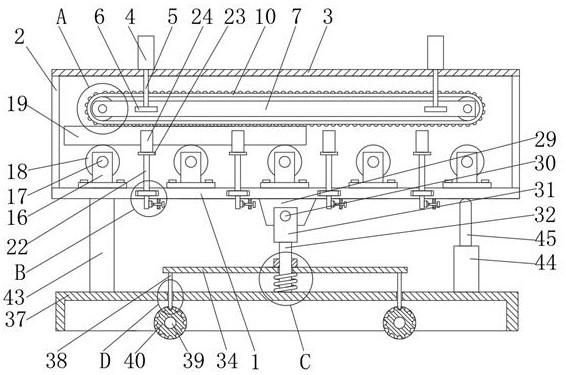
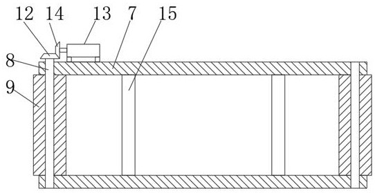
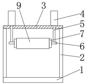
[0029] A crane end beam delivery workbench, comprising a support platform 1, four columns 2 are fixedly connected to the upper end of the support platform 1, and a support plate 3 is fixedly connected to the upper ends of the four columns 2, and the support plate 3 Four first cylinders 4 are fixedly installed on the upper end of the four first cylinders 4, and the first cylinder rods 5 of the four first cylinders 4 are slidably connected with the support plate 3, and the lower end of each first cylinder 4 is fixedly connected with a connecting seat 6 Each of the two connecting seats 6 is fixedly connected with a shaft frame 7, a connecting frame 15 is fixedly connected between the two shaft frames 7, and a roller shaft 8 is connected to the shaft frame 7 in rotation. The outer side of the shaft 8 is fixedly connected with a transmission roller 9, the transmission roller 9 is in contact with the axle frame 7, and the outer side of the transmission roller 9 is sleeved with a conv...


PUM


Abstract

The invention discloses a crane end beam conveying workbench, comprising a support platform, four columns are fixedly connected to the upper end of the support platform, and a support plate is fixedly connected to the upper ends of the four columns, and the upper end of the support plate Four first cylinders are fixedly installed, and the first cylinder rods of the four first cylinders are slidingly connected with the support plate. The lower end of each of the first cylinders is fixedly connected with a connecting seat, and every two connecting seats A shaft frame is fixedly connected to the top, a connecting frame is fixedly connected between the two shaft frames, a roller shaft is rotatably connected inside the shaft frame, and a transmission roller is fixedly connected to the outer side of the roller shaft, and the transmission roller and The axle frames are in contact with each other, and a conveyor belt is sleeved on the outer side of the transmission roller, and the surface of the conveyor belt is provided with protrusions. The invention relates to a crane end beam conveying workbench, which has the characteristics of good conveying effect, good applicability and convenient movement.

Description

technical field [0001] The invention belongs to the technical field of transportation devices, in particular to a crane end beam transportation workbench. Background technique [0002] A crane refers to a multi-action hoisting machine that lifts vertically and carries heavy objects horizontally within a certain range. Cranes generally have bridges, which are composed of main girders and end girders. The working characteristic of the crane is to do intermittent movement, that is, the corresponding mechanisms for the actions of retrieving, moving, and unloading in a working cycle work alternately. The development and use of cranes in the market are becoming more and more extensive. During the production process of the crane, its end beam needs to be welded with other parts, but the end beam is relatively heavy, and generally requires a special end beam delivery workbench for transportation, and transports it to a designated area to facilitate welding work. However, there are...

Claims


Application Information

Patent Timeline
Patent Type & Authority Patents(China)
IPC IPC(8): B65G15/30B65G15/60B65G21/12B65G23/04B65G23/22B65G47/34B65G47/24B65G41/00
CPCB65G15/30B65G15/60B65G21/12B65G23/04B65G23/22B65G41/001B65G47/24B65G47/34
Inventor 李培峨
Owner 烟台市特种设备检验研究院
Learn More