Railway bridge ballast blocking wall mold moving device and method

A technology of mold movement and ballast wall, applied in bridges, hoisting devices, bridge construction and other directions, can solve problems such as increasing costs, and achieve the effects of easy movement, low cost and simple structure

Active Publication Date: 2021-04-27
SHANDONG UNIV
View PDF7 Cites 0 Cited by
  • Summary
  • Abstract
  • Description
  • Claims
  • Application Information

AI Technical Summary

Problems solved by technology

However, the inventor found that the weight of the mold is difficult to lift and transport by individuals alone, and calling large motor vehicles to hoist low wall molds often outweighs the gain and increases the cost

Method used


Image

  • Railway bridge ballast blocking wall mold moving device and method
  • Railway bridge ballast blocking wall mold moving device and method
  • Railway bridge ballast blocking wall mold moving device and method

Examples


Embodiment 1

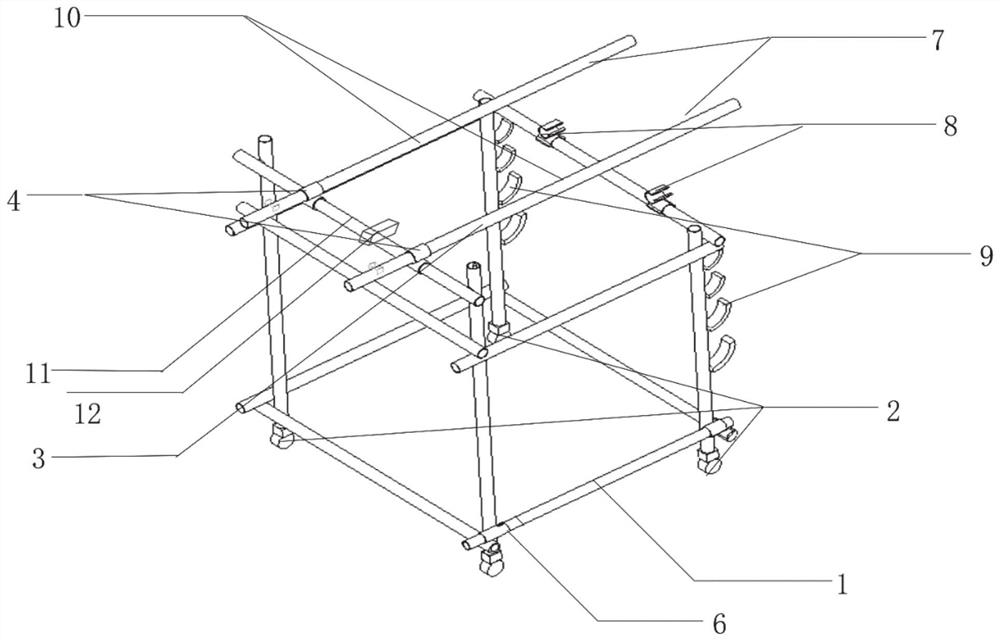
[0035] This embodiment provides a railway bridge ballast wall mold moving device, such as figure 1 As shown, it includes a bracket 1, a lifting lever 3, a universal wheel 2, and a counterweight hook 9. The lifting lever 3 is installed above the bracket 1, and the bottom of the bracket 1 is equipped with a universal wheel 2; heavy hook9.

[0036] Further, the support 1 is a frame structure, which is connected by a plurality of horizontal bars and vertical bars to form a cube structure; the bars are connected by fixed locks 6 . The fixed lock 6 is a cross lock. In this embodiment, the bracket 1 is made of waste steel pipes on site, without additional cost. Preferably, a steel pipe with a diameter of φ50 is rotated. Of course, in other embodiments, steel pipes of other sizes can also be selected according to the weight of the mould.

[0037] A support rod 11 is connected between the two longitudinal rods at one end, and the lifting lever 3 is installed above the support 1 thr...

Embodiment 2

[0046] This embodiment provides a method for installing a railway bridge ballast wall mold moving device, comprising the following steps:

[0047] Step (1) Connect the steel pipes to each other by using the fixed lock 6 to form the bracket 1 . According to the site conditions, you can choose the reinforcement measures yourself. It is necessary to ensure that the upper and lower ends of the four longitudinal rods of the bracket 1 have sufficient length reserved, the lower end is used to install the universal wheel 2, and the upper end is used to install the lifting lever 3.

[0048] Step (2) Install the universal wheel 2 on the bottom of the four longitudinal rods of the bracket 1.

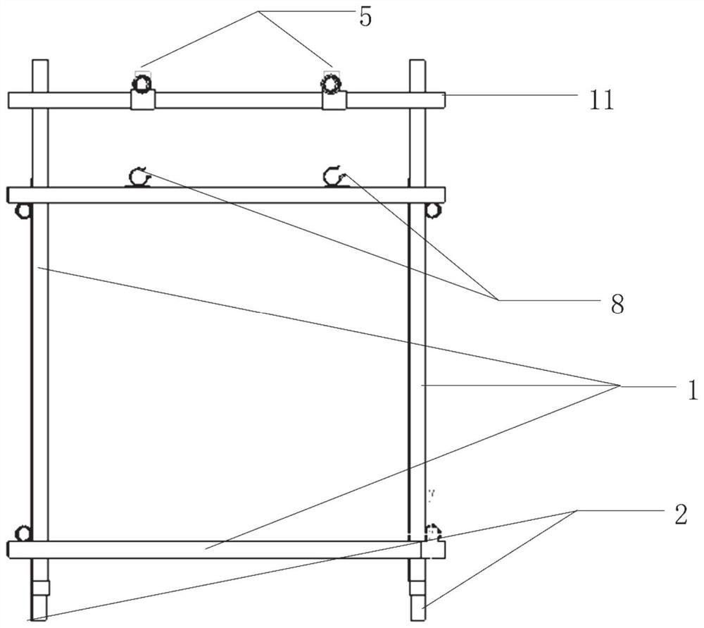
[0049] Step (3) Install support rods 11 across the upper ends of the two vertical rods on the same side, and the support rods 11 are connected to the vertical rods with fixed locks 6 .

[0050] Step (4) Install a certain number of movable locks 4 in the middle of the support rod 11 to ensure that...

Embodiment 3

[0056] This embodiment provides a method for moving a railway bridge ballast wall mold, using the moving device described in Embodiment 1, including the following steps:

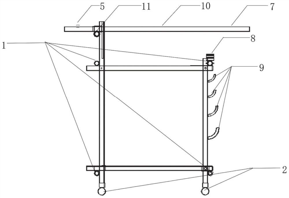
[0057] Step (1) Use the laser rangefinder 12 to accurately position the mold, push the mobile mold base to the corresponding position, and put the lifting rope on the mold on the lifting side of the lifting lever 3; the fixed position of the lifting rope is located between the anti-skid hook 5 and the movable lock Buckle between 4.

[0058] Step (2) Press down the holding part 7 to lift the mold.

[0059] Step (3) as Figure 4 As shown, the grip part 7 is fixed to the cross bar of the bracket 1 through the opening and closing lock 8 , and the operator releases the grip part 7 .

[0060] Step (4) According to the site conditions, hang a certain weight of counterweight on the counterweight hook 9, and wait for the device to be stable to ensure that it can be moved after overturning does not occur.


PUM


Abstract

The invention discloses a railway bridge ballast blocking wall mold moving device and method. The device comprises a support, a plurality of hoisting levers used for hoisting a mold are installed at the top of the support, and laser range finders are arranged between the hoisting levers. The hoisting levers can rotate relative to the support, an opening and closing lock catch fixed to the support is arranged below the other end of each hoisting lever, and the rotated hoisting levers can be clamped and fixed through the opening and closing lock catches. According to the device, the mold can be hoisted and moved quickly, safely, economically and conveniently.

Description

technical field [0001] The invention relates to the construction field of railway beam retaining ballast walls, in particular to a mold moving device and method for railway bridge retaining ballast walls. Background technique [0002] Ballast retaining walls are installed on the bridge decks of railway ballast tracks to protect the ballast. At present, most railway beam retaining walls adopt concrete structure, and molds are required for pouring railway beam retaining walls. However, the inventor found that the weight of the mold is difficult to lift and transport by individuals alone, and calling large motor vehicles to hoist the low wall mold is often not worth the candle, which increases the cost. Contents of the invention [0003] In view of the deficiencies in the prior art, the object of the present invention is to provide a railway bridge ballast wall mold moving device and method, which can lift and move the mold quickly, safely, economically and conveniently. [...

Claims


Application Information

Patent Timeline
Patent Type & Authority Applications(China)
IPC IPC(8): B66F15/00B66F13/00B66F17/00E01D21/00
CPCB66F15/00B66F13/00B66F17/00E01D21/00
Inventor 石少帅郭伟东吴琪曹天宇王利戈李术才卜林刘进佩王康
Owner SHANDONG UNIV
Why Eureka
Try Eureka