Voltage division proportion adjusting circuit, switch control circuit and cooking utensil

A switch control circuit, proportional adjustment technology, applied in induction heating control, household appliances, electric heating fuel, etc., can solve the problem that the synchronous circuit is difficult to meet the requirements of work and so on

Pending Publication Date: 2021-04-27
GREE ELECTRIC APPLIANCES INC
View PDF0 Cites 0 Cited by
  • Summary
  • Abstract
  • Description
  • Claims
  • Application Information

AI Technical Summary

Problems solved by technology

[0004] Therefore, the technical problem to be solved by the present invention is to overcome the problem that the traditional single synchronous circuit in the prior art is dif

Method used


Image

  • Voltage division proportion adjusting circuit, switch control circuit and cooking utensil
  • Voltage division proportion adjusting circuit, switch control circuit and cooking utensil
  • Voltage division proportion adjusting circuit, switch control circuit and cooking utensil

Examples


Embodiment 1

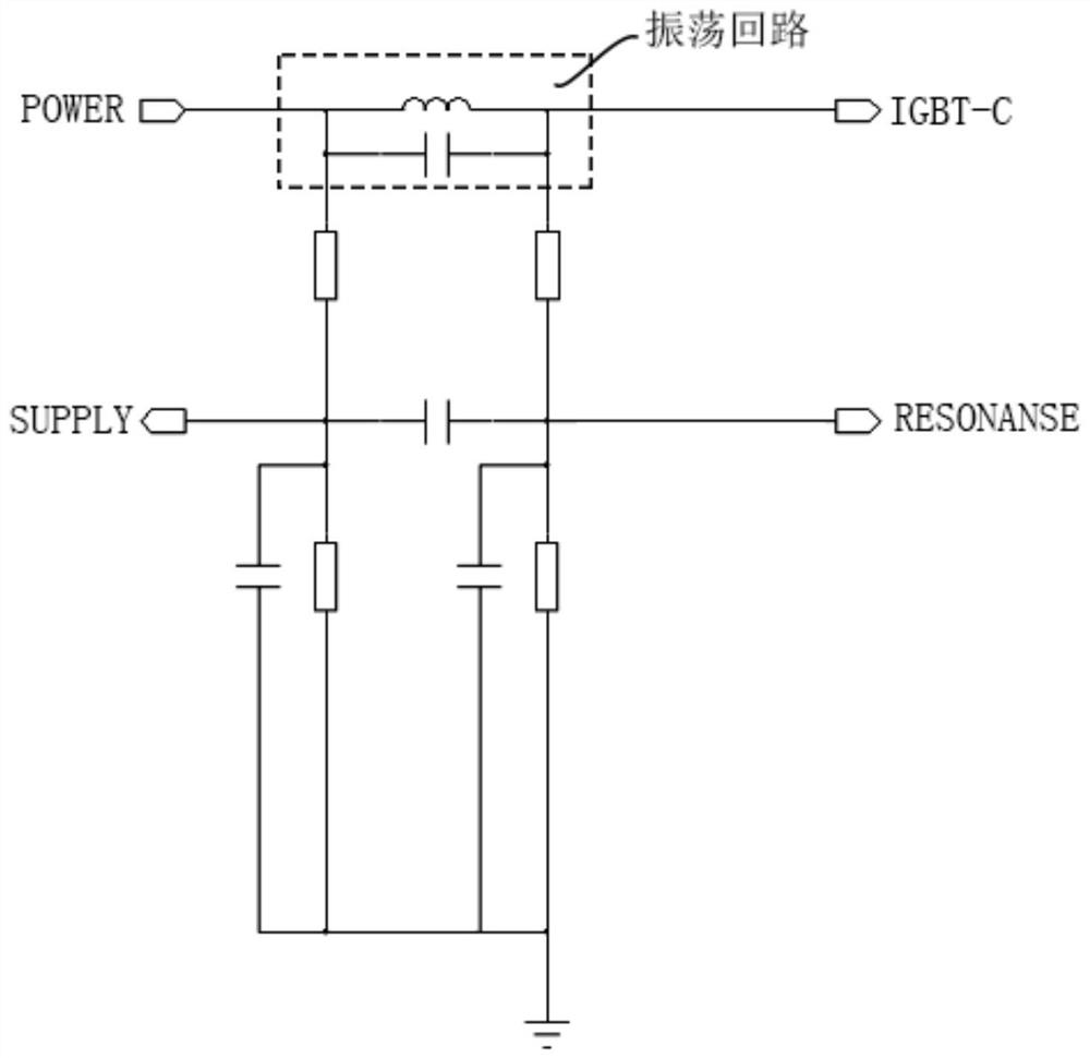
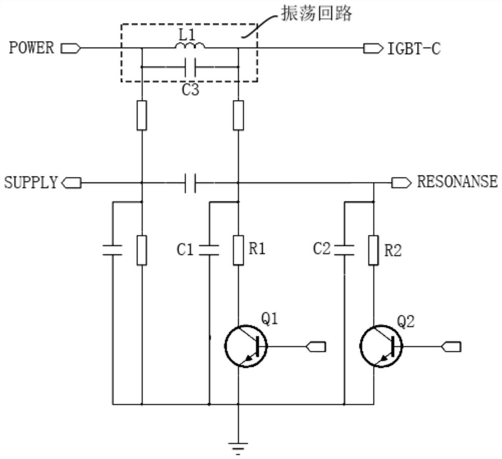
[0041] Such as figure 2 As shown, the embodiment of the present invention provides a voltage division ratio adjustment circuit, the voltage division ratio adjustment circuit includes: an oscillation circuit, a first voltage detection terminal SUPPLY, a second voltage detection terminal RESONANCE, a first adjustable resistance and a second Adjustable resistance.

[0042] The first end of the oscillating circuit is used to connect to the power supply, and the second end of the oscillating circuit is used to connect to the resonance end of the IGBT module. The first voltage detection terminal SUPPLY is connected to the first end of the oscillation circuit through the first resistor R3, and the first voltage detection terminal SUPPLY is used to detect the voltage shared by the first adjustable resistor. The second voltage detecting terminal RESONANCE is connected to the second terminal of the oscillation circuit through the second resistor R4, and the second voltage detecting te...

Embodiment 2

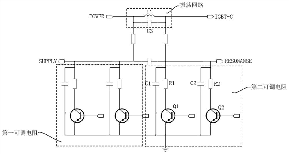
[0053] Such as Figure 4 As shown, the embodiment of the present invention also provides a switch control circuit, which includes a control module, an IGBT module, and the voltage division ratio adjustment circuit described in the above-mentioned embodiments.

[0054] The first input terminal of the control module is connected to the first voltage detection terminal SUPPLY, the second input terminal of the control module is connected to the second voltage detection terminal RESONANCE, and the first output terminal of the control module is connected to the The control terminal of the IGBT module is connected, and the control module is also provided with a plurality of second output terminals, and the control module sends control to the switch modules of the multiple resistance modules in the voltage division ratio adjustment circuit through the second output terminals. Signal; the other end of the IGBT module is grounded, that is, the E pole of the IGBT module is grounded.

[...

Embodiment 3

[0064] An embodiment of the present invention also provides a cooking appliance, which includes: the voltage division ratio adjustment circuit described in any one of the above embodiments, and / or the switch control circuit described in any one of the above embodiments.


PUM


Abstract

The invention discloses a voltage division proportion adjusting circuit, a switch control circuit and a cooking utensil. The voltage division proportion adjusting circuit comprises: an oscillation loop, wherein a first end of the oscillation loop is used for being connected with a power supply, and a second end of the oscillation loop is used for being connected with a resonance end of an I GBT module; a first voltage detection end which is connected with the first end of the oscillation circuit through a first resistor; and a second voltage detection end which is connected with the second end of the oscillation circuit through a second resistor; The voltage division proportion adjusting circuit further comprises: a first adjustable resistor, wherein one end of the first adjustable resistor is connected with the first voltage detection end, and the other end of the first adjustable resistor is grounded; and/or a second adjustable resistor, wherein one end of the second adjustable resistor is connected with the second voltage detection end, and the other end of the second adjustable resistor is grounded. Thus, when the voltage of the mains supply is low or high, the resistance value of the first adjustable resistor or the resistance value of the second adjustable resistor is adjusted, so that the I GBT module can be normally conducted.

Description

technical field [0001] The invention relates to the field of electronic circuits, in particular to a voltage division ratio adjustment circuit, a switch control circuit and a cooking utensil. Background technique [0002] Existing common electromagnetic heating cooking appliances such as induction cooker and IH rice cooker generally use single-tube parallel resonant electromagnetic induction heating technology. In single-tube parallel resonant electromagnetic induction heating technology, a synchronous circuit is needed to compare and detect the voltage of the power supply terminal and the resonance terminal. When When the resonance terminal voltage is zero, the power device IGBT is turned on. [0003] At present, in order to make the product work in a wide voltage range, such as 80V ~ 270V, the traditional single synchronous circuit is difficult to meet the requirements. Because at high voltage, the resonance terminal voltage has not reached zero, but the IGBT has been con...

Claims


Application Information

Patent Timeline
IPC IPC(8): H05B6/06F24C7/08
CPCF24C7/082H05B6/06
Inventor 邱健唐军荣周世燕夏乙珩徐朋亮
Owner GREE ELECTRIC APPLIANCES INC
Why Eureka
Try Eureka