Battery sensor for temperature-independent current measurement using shunt

A battery sensor and shunt technology, which is applied in the direction of measuring electricity, measuring electrical variables, and components of electrical measuring instruments, etc., can solve problems such as direct placement of contacts for measuring shunt voltage.

Pending Publication Date: 2021-04-27
CONTINENTAL AUTOMOTIVE TECH GMBH
View PDF0 Cites 0 Cited by
  • Summary
  • Abstract
  • Description
  • Claims
  • Application Information

AI Technical Summary

Problems solved by technology

[0006] Since it is currently technically impossible to place the contacts for measuring the shunt voltage directly at the weld seam between the resistance alloy and the connection part and it is also disadvantage...

Method used


Image

  • Battery sensor for temperature-independent current measurement using shunt
  • Battery sensor for temperature-independent current measurement using shunt
  • Battery sensor for temperature-independent current measurement using shunt

Examples


Embodiment Construction

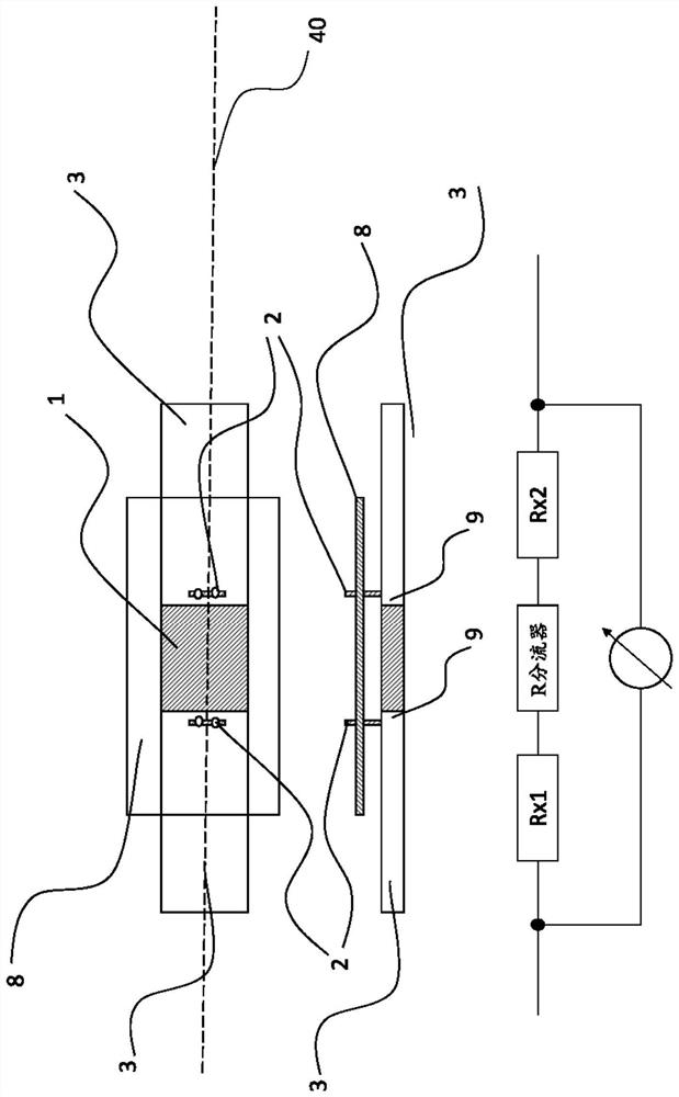
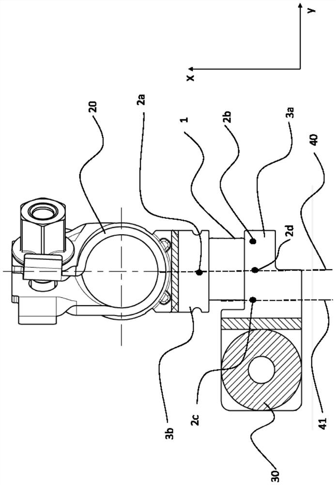
[0033] exist figure 1A common battery sensor is schematically shown in . The battery current is measured according to the shunt principle, wherein the voltage drop at the shunt resistor caused by the current to be measured is measured according to Ohm's law and with the aid of calibration parameters which ultimately represent the resistance value of the shunt at the respective operating point ) to convert the measured voltage drop into a current value. The heart of a shunt is the measurement path defined by the tap point (2) for the shunt voltage to be measured and usually contains a dedicated resistive alloy (1). The resistance alloy (1) is fixedly connected (for example welded) to the connecting element (3) on opposite sides viewed in the direction of current flow. The connection part is used to connect the shunt to the circuit to be measured. A connecting part is thus designed, for example, as an adapter ( 30 ) for connecting (screwing, clamping, soldering) current cable...


PUM


Abstract

The invention relates to a battery sensor, in particular for a vehicle battery, having two connection parts (3a, 3b) which are electrically conductively connected to each other via a resistor element (1), there being one contact point (2a, 2b) on each of the connection parts (3a, 3b), the direction of the longitudinal axis of at least one of the connection parts (3a, 3b) deviating from the direction of the longitudinal axis of the resistor element or shunt (1). The position of the contact points (2a, 2b) is selected transversely to the longitudinal axis of the resistor element or shunt such that the electrical resistances (R4, R5, R6) of sections of the connection parts (3a, 3b) through which the current flows transversely to the longitudinal axis (y-direction) of the resistor element or shunt are dimensioned such that a temperature-induced change in the electrical resistances (R4, R5, R6) compensates for a temperature-induced change in electrical resistances (R3) formed by sections of the connection parts (3a, 3b) through which current flows in the direction of the longitudinal axis of the resistor element or shunt.

Description

technical field [0001] The invention relates to a battery sensor, in particular for a vehicle battery, with two connecting parts, which are connected to each other in an electrically conductive manner by means of a resistive element, wherein each of the connecting parts is provided with There is a contact part. Background technique [0002] Battery sensors for determining the battery state of motor vehicle batteries have been commercially available for some time. Common battery sensors can be integrated into connection terminals for connecting battery cables to battery poles. [0003] Such battery sensors usually contain means for measuring the battery voltage, the battery current received or delivered by the battery and the temperature measured in the components of the battery sensor. Battery sensors also typically contain a microcontroller that buffers the measured data, filters it, and calculates other battery variables from it (such as state of charge, internal resista...

Claims


Application Information

Patent Timeline
IPC IPC(8): G01R1/20G01R31/364H01C7/06H01M50/569
CPCG01R1/203G01R31/364G01R31/374H01C7/06H01M10/48H01M2220/20H01M2200/00Y02E60/10H01M50/569
Inventor M·施拉梅H·弗伦策尔A·奥默尔
Owner CONTINENTAL AUTOMOTIVE TECH GMBH
Why Eureka
Try Eureka