[0063]The following is a specific embodiment of the present invention and a further description of the technical solutions of the present invention, but the present invention is not limited to these embodiments.
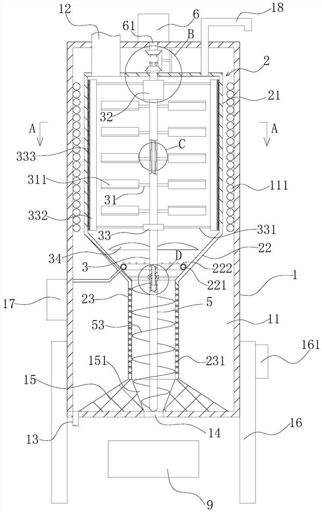
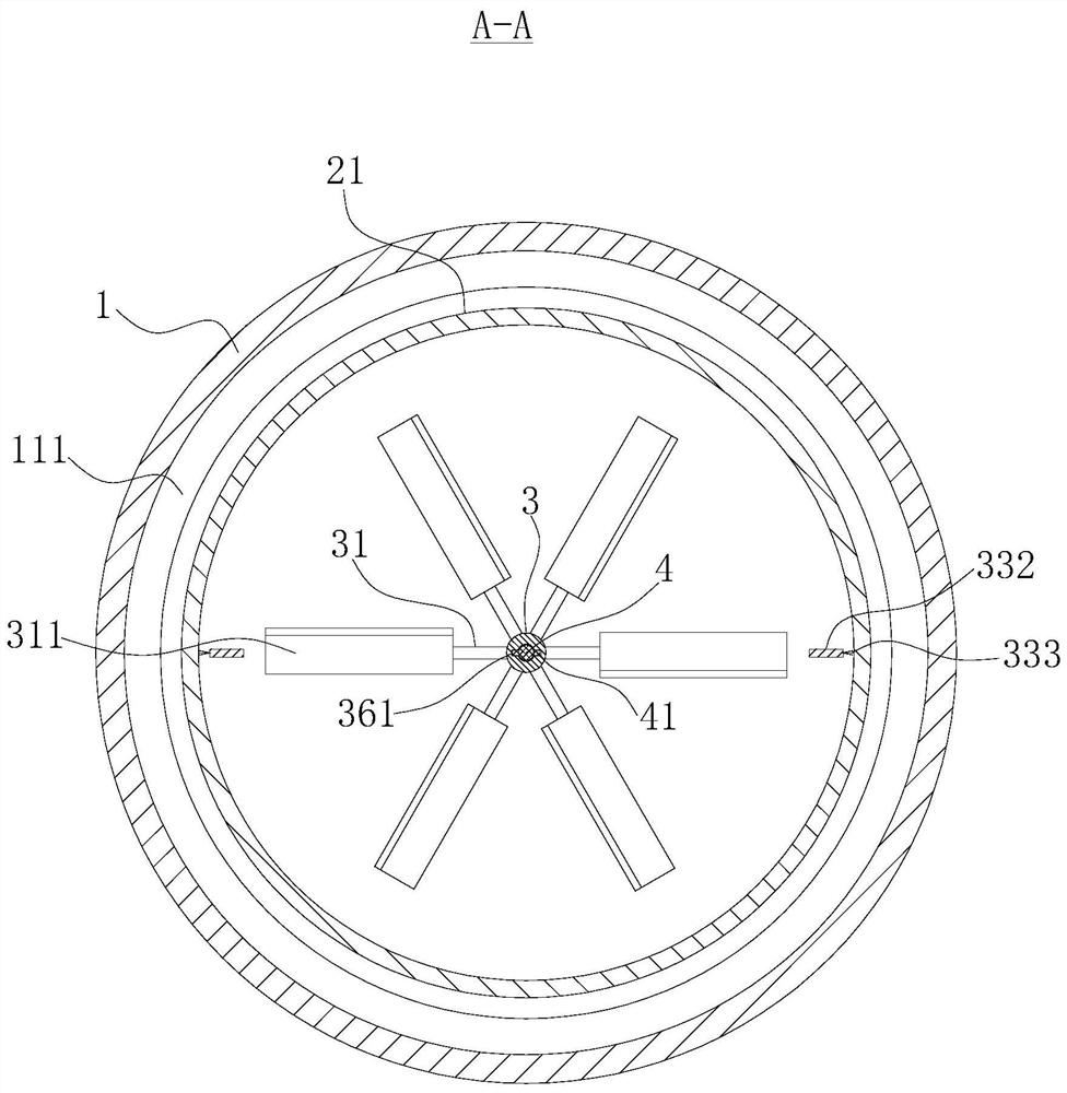
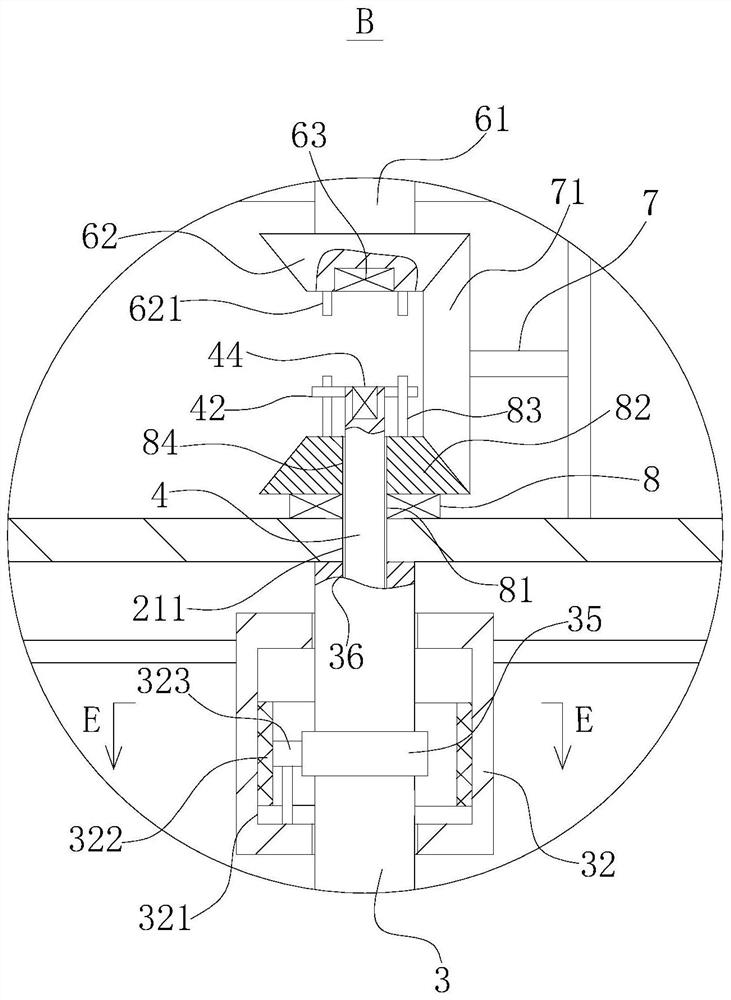
[0064]Such asFigure 1 to 6As shown, a fish cooking pulverizer includes a cylindrical body 1, a stirring cylinder 2, an electric heating tube 111, a stirring mechanism, a drive mechanism, a stranded mechanism, and an extrusion mechanism.
[0065]The cylinder 1 is provided with a cavity 11, and the top of the cylinder 1 is fixedly coupled, and the bottom of the cylinder 1 is provided with a discharge hole 14, the cylinder 1 outer side wall There are several support legs 16 in the circumferential direction.
[0066]The stirring bar 2 is mounted in the cavity 11 which is sequentially connected from top to bottom, and the tapered portion 22 and the second straight cylinder portion 23 are sequentially connected. The first straight cylinder portion 21 The coaxial rotation is provided with a first rotating shaft 3, and the lower end of the second straight portion 23 is in communication with the discharge hole 14, and the feed tube 12 is in communication with the upper end of the first straight cylinder portion 21.
[0067]Preferably, a conveyor belt 9 is provided below the discharge hole 14, the transmission belt 9 can be delivered to the preliminary dehydrated fish.
[0068]The electric heating tube 111 is disposed within a cavity 1 located outside of the first straight cylindrical portion 21, and a electric heating wire is provided with an electric heating wire.
[0069]The stirring mechanism is disposed on the first rotating shaft 3, and when the first rotating shaft 3 is rotated clockwise, the mixing mechanism can move the fish in the first straight cylindrical portion 21, and when the first axis 3 is rotated counterclockwise, The agitation mechanism can move downward movement of the fish in the first straight cylindrical portion 21.
[0070]The drive mechanism is disposed at the top of the cavity 11, the drive mechanism capable of rotating the first shaft 3.
[0071]The strand mechanism is disposed within the tapered portion 22, which is capable of simultaneously mushing to the fish in the tapered portion 22 using the rotation of the first rotating shaft 3.
[0072]The extrusion mechanism is disposed within the second straight portion 23, and when the first rotating shaft 3 is rotated counterclockwise, the extrudation mechanism can extrud the fish in the second straight portion 23 to the discharge hole 14, At the same time, the fish is preliminaryly dehydration, and when the first axis 3 is rotated clockwise, the extrusion mechanism can push the fish in the lower end of the tapered portion 22 to the upper end of the tapered portion 22.
[0073]The fish is entered into the stirring cylinder 2 through the feed tube 12, and the electric heating wire in the electric heating tube 111 is activated, and the fish material in the first straight cylinder portion 21 is heated, and the activation drive mechanism drives the first shaft 3 clockwise to rotate, pass The stirring mechanism causes the fish in the bottom of the first straight cylindrical portion 21 to move up, increase the heat transfer time of the fish, increase the cooking efficiency, and the fish is integrated upward, and the fish is attached to the inner wall of the first straight cylinder portion 21 to ensure The fish is well received, improves the cooking effect, when the fish is cooked, drive the first rotating shaft 3 counterclockwise to rotate, so that the fish in the first straight cylindrical portion 21 moves downward into the tapered portion 22, while starting The strand mechanism, strands the fish in the tapered portion 22, while activating the extrusion mechanism, extruding the filament after the mirror is blocked, avoiding the discharge hole 14 by the fish, affecting the cooking efficiency It can also perform preliminary dehydration treatment to the fish, shorten the next step, and the energy saving is efficient; in addition, when the extrusion mechanism can also push the fish in the lower end of the tapered portion to the upper end of the tapered portion, avoid fish in the cone The lower end of the department is stacked, causing over-cooking.
[0074]Specifically, the bottom of the cavity 11 is coaxially solidified with a round counter, and the upper and small tapered holes 151 are opened in the round counter, the lower end of the second straight portion 23 and the upper end of the round counter 15. Solid, the second straight portion 23 is connected to the discharge hole 14 through the tapered hole 151.
[0075]When the extrusion mechanism extrudes the fish in the second straight portion 23 to the cone hole 151, since the cone hole 151 is present to a lower tapered tapered, the fish is moved downward to the cone hole 151, The movement speed is slowed, and the pressure in the second straight portion 23 is increased, and the amount of dehydration of the fish is increased.
[0076]Specifically, the mixing mechanism includes several agitation structures, and several of the agitating structures are uniformly disposed at the first rotating shaft 3 located within the first straight cylindrical portion 21 in the longitudinal direction, including several first. A fixed bar 31.
[0077]Several first fixing rods 31 are disposed on the first rotating shaft 3 in the circumferential direction, and the first fixing rod 31 is secured from one end level of the first rotating shaft 3, and the blade plate 311 is fixed, when the first axis 3 clockwise When rotating, the turning plate 311 is lower than the back side of the front side, and when the first rotating shaft 3 is rotated counterclockwise, the turntable plate 311 is higher than the rear side side.
[0078]When the drive mechanism drives the first axis 3 to turn clockwise, the rotary plate 311 is lower than the rear side side, and the turning plate 311 rotates the fisser in front of the blade plate 311, when all the blade plates When the 311 is rotated, the fish in the first straight cylindrical portion 21 is integrated upward, so that the fish in the first straight cylindrical portion 21 constantly changes the position, so that the fish is well received, and the heat of the fish is increased, and the cooking efficiency is improved. When the drive mechanism drives the first rotating shaft 3 counterclockwise, the rotary blade 311 is higher than the rear side side by the front side, and the turning plate 311 rotates the fish in front of the blade plate 311 moves downward, when all rot leaves When the plate 311 is rotated, the fish in the first straight cylindrical portion 21 is integrated downward, and the fish is moved to the tapered portion 22 to improve the discharge efficiency of the fish.
[0079]Specifically, the stranded mechanism includes a fixing plate 37 and a plurality of stirring blades 34.
[0080]The fixing plate 37 is fixed to the lower end of the tapered portion 22 by a plurality of third fixing rod 372, and the lower end of the first rotating shaft 3 is rotated on the upper side of the fixing plate 37.
[0081]Several of the agitating blade 34 is disposed on the first rotating shaft 3 located within the tapered portion 22 along the circumferential direction.
[0082]When the fish is cooked, the start drive mechanism drives the first axis 3 counterclockwise to rotate, push the fish to move downward, and the stirring blade on the first rotating shaft 3 rotates, and the fish in the tapered portion 22 will be lame Broken, avoid the fishes blocking the discharge hole 14.
[0083]Specifically, the drive mechanism includes a second axis 61, a third rotating shaft 7, a fourth axis 8, and a first link structure.
[0084]The second shaft 61 is vertically rotated at the top of the cavity 11, and the lower end of the second rotating shaft 61 is coaxially solids a first cone gear 62, and a motor 6 is provided with a motor 6, which is provided. The upper end of the second shaft 61 is inserted and the end portion and the output shaft of the motor 6 are solid.
[0085]The third rotating shaft 7 is horizontally disposed above the agitation cylinder 2, and the second tapered gear 71 is provided on the third rotating shaft 7, the second cone gear 71, and the first cone gear 62 mesh.
[0086]The fourth rotating shaft 8 is rotated at the top of the agitating cylinder 2, and the upper end of the fourth rotating shaft 8 is coaxially solids a third cone gear 82, and the third cone gear 82 and the second cone gear 71 mesh. The top portion of the first straight cylindrical portion 21 is provided with a perforation 211, and a fourth through hole 81 is opened, and a fifth through hole 84 is opened on the third cone gear 82. The fifth pass. The hole 84, the fourth through hole 81, and the perforation 211 are allocated, and the upper end of the slider 4 is sequentially passed through the perforation 211, the fourth through hole 81, and the fifth through hole 84 extend above the third cone gear 82.
[0087]Preferably, the perforation 211, the fourth through hole 81, and the fifth through hole 84 are the same.
[0088]The first link structure is disposed on the first cone gear 62 and the third cone gear 82, the first linkage structure enables the slider 4 to drive the first bevel gear 62 and the third cone gear 82, respectively.
[0089]When the fish is needed, the slider 4 is transmitted to the first cone gear 62 through the first communication structure, and the start motor 6 drives the second axis 61 clockwise, and drives the first cone gear 62 and the slider 4. Turn clockwise, the turning plate 311 pushes the fish material in the first straight cylindrical portion 21, increasing the heat-insulating time of the fish; when the cooking requires discharge the fish, the slider 4 and the third The bevel gear 82 is driven, and the start motor 6 drives the second axis 61 clockwise, and the third cone 62 is driven by the first cone gear 62, the second cone gear 71 is driven counterclockwise, and the blade plate 311 pushes the first The fish in the tubular portion 21 moves downward, and improves the discharge efficiency of the fish.
[0090]Specifically, the first communication structure includes two third lever 83, two second gear rods 621, two upper lever 42, first electromagnet 44, and a second electromagnet 63.
[0091]The two third lever 83 is disposed on the upper end surface of the third cone gear 82, and the third lever 83 is symmetrically disposed on both sides of the fifth through hole 84.
[0092]The two of the second lens 621 are vertically fastened to the lower end surface of the first cone gear 62, and the two second lever 621 are located directly above the two third lever 83.
[0093]Two of the upper upper lever 42 are symmetrically disposed on both sides of the upper end of the slide rod 4, and the distance between the outer end of the two upper liner 42 is greater than the distance between the two third lever 83.
[0094]When the two upper line 42 contacts the lower end surface of the first cone gear 62, the two second lens 621 rotate can push the two upper pion bars 42 and the slider 4 to rotate, and when the two upper lever 42 contacts the third When the upper end surface of the cone gear 82, two of the third lever 83 rotate can drive two upper lever 42 and the slider 4 rotation.
[0095]The first electromagnet 44 is embedded on the upper end surface of the slider 4, the second electromagnet 63 is embedded on the lower end surface of the first cone gear 62, wherein a controller 161 is provided on the leg 16, The first electromagnet 44 and the second electromagnet 63 are electrically connected to the controller 161.
[0096]When stirring is required to be stirred, the first electromagnet 44 and the second electromagnet 63 are activated, and the first electromagnet 44 and the magnetic pole of the second electromagnet 63 are opposite to the attractive force, and the suction slider 4 is moved upward. The first bevel gear 62 is in the same horizontal plane with the two second lever 621, and then activates the motor 6 to drive the second axis 61 and the first cone gear 62 clockwise, the first cone gear 62 The two second lever 621 rotate push two upper pion bars 42 and the slider 4 follow clockwise; when the fish is required, the first electromagnet 44 and the second electromagnet 63 are simultaneously activated, so that the first electromagnetic The magnetic pole of the iron 44 and the second electromagnet 63 is the same, and the repulsive force is generated. The push rod 4 is moved downward to contact the third cone 82, and the two upper lever 42 and the two third lever 83 are in the same horizontal plane, The motor 6 is then started to drive the second axis 61 and the first cone gear 62 clockwise, and the third bevel gear 82 is rotated counterclockwise by the second cone gear 71, and the two third lever 83 on the third cone gear 82 rotates. Push two up-to-dial 42 rods and slide rods 4 followed by counterclockwise, simple operation, saving time and effort.
[0097]Specifically, the extrusion mechanism includes a rotating shaft 5, a spiral guide groove 53, a plurality of drains apertures 231, a drain pipe 13, and a second link structure.
[0098]The rotating shaft 5 is rotated in the second straight portion 23, and the upper end of the rotation shaft 5 is rotated on the lower side of the fixing plate 37, and the lower end of the rotation shaft 5 extends into the tapered hole 151.
[0099]The spiral guide groove 53 is fixed to the rotating shaft 5 in the longitudinal direction.
[0100]Several of the drain holes 231 are opened on the side wall of the second straight portion 23, the drain hole 231 being connected to the cavity 11.
[0101]The lower end of the cylinder 1 is connected to a drain pipe 13, and the drain pipe 13 is in communication with the bottom of the cavity 11.
[0102]The second link structure is disposed on the upper end of the rotating shaft 5, and when the first rotating shaft 3 is rotated counterclockwise, the second link structure can simultaneously drive the rotation shaft 5 counterclockwise.
[0103]When the fish is discharged, the start motor 6 drives the second axis 61 clockwise to rotate, and the third cone gear 62 and the second bevel gear 71 are driven to rotate counterclockwise, so that the first axis 3 Returning counterclockwise, by the second link structure, the rotation shaft 5 and the spiral guide groove 53 are rotated counterclockwise, and the fish that enters the second straight portion 23 is squeezed to the discharge hole 14, the portion of the fish The moisture is discharged through the drainage hole 14 during extrusion, and the preliminary dehydration of the fish is realized, and the time of the next step is shortened.
[0104]Specifically, the second link structure includes a second through hole 371, a mounting chamber 51, two first lever 52.
[0105]The second through hole 371 is opened to the fixing plate 37, the first through hole 36 and the second through hole 371 up and down.
[0106]Preferably, the second through hole 371 has a pore size greater than the aperture of the first through hole 36.
[0107]The mounting chamber 51 is opened within the rotation shaft 5, and the third through hole 511 is opened on the upper end surface of the rotation shaft 5, and the third vent 511 is in communication with the mounting chamber 51, the second through hole 371. The same axis of the third through hole 511, preferably, the second through hole 371, and the third through hole 511, the second through end of the slider 4 sequentially passes through the second through hole 371 and the third through hole. 511 and the end extends into the mounting chamber 51, two down-lever 43 is provided in the end portion of the slider 4 in the mounting chamber 51.
[0108]The two first lever 52 is vertically fastened to the bottom of the mounting chamber 51, and the distance between the outer ends of the lower lower lever 43 is greater than the distance between the two first lever 52.
[0109]When the fish is needed, the first electromagnet 44 and the second electromagnet 63 are started, the magnetic pole of the first electromagnet 44 and the second electromagnet 63 is the same, and the repellent force is generated, and the slider 4 is moved downward. When the two upper pion bars 42 in the upper end of the slider 4 are in the same horizontal plane in the same horizontal plane, the start motor 6 drives the second axis 61 clockwise, and by the first cone gear 62 and the second cone gear 71 The third cone gear 82 and the slider 4 are rotated counterclockwise, and the first rotating shaft 3 is rotated counterclockwise, and the rotary plate 311 rotates to move the fish in the first straight cylindrical portion 21, into the tapered portion 22, and stirred in the blade 34 strands, and the lower chaler 43 at the lower end of the slider 4 drive the rotation shaft 5 and the spiral guide groove 53 counterclockwise to discharge the fisser in the second straight portion 23 to the discharge. The hole 14, the discharge speed of the fish is simple, and the structure is simple; in addition, when the fish is needed, the first electromagnet 44 and the second electromagnet 63 are started, and the magnetic pole of the first electromagnet 44 and the second electromagnet 63 is reversed. Attractive, pull the slider 4 upward movement, when the two upper lever 42 in the upper end of the slider 4 is in the same horizontal plane in the same horizontal plane, the start motor 6 drives the second axis 61 clockwise. The rotating blade 311 is rotated clockwise by the first axis 61, and the fish in the first straight cylinder portion 21 is stirred up, and the lower lever 43 at the lower end of the slider 4 drives the rotation shaft 5 by two first lever 52 and The spiral guide groove 53 rotates clockwise, and the fish falling to the lower end of the tapered portion 22 is pushed to the upper end of the tapered portion 22, and the fish is circulated and heated.
[0110]Specifically, a scraper mechanism is also provided, and the squeegee mechanism is disposed on the first rotating shaft 3 including a first sleeve 32, a second sleeve 33, a blade 332, a ring groove 321, The second gear 35 and the first gear 323.
[0111]The first sleeve 32 and the second sleeve 33 are all up and down coaxial rotations on the first rotating shaft 3 located within the first straight cylindrical portion 21.
[0112]The scraper 332 is disposed between the first sleeve 32 and the second sleeve 33 by two second fixing rods 331, and the length direction of the blade 332 and the length direction of the first spindle 3 are parallel. The width direction and the radial direction of the blade 332 and the first straight cylindrical portion 21 are disposed adjacent to one side of the first straight cylindrical portion 21 having a brush 333, and the brush 333 The free end is in contact with the inner side wall of the first straight cylinder portion 21.
[0113]The annular groove 321 is opened on the inner side wall of the first sleeve 32, the annular groove 321, away from one side of the first rotating shaft 3, and a ring gear 322;
[0114]The first spindle 3 in the annular groove 321 is solids a second gear 35;
[0115]The first gear 323 rotates on the lower side wall of the annular groove 321, the first gear 323 engages the ring gear 322, and the second gear 35, respectively.
[0116]When the first axis 3 is rotated clockwise, the second gear 35 is driven clockwise, and the ring gear 322 and the first sleeve 32 in the annular groove 321 are rotated counterclockwise through the first gear 323, so that the blade 332 is along The inner side wall of the first straight cylinder portion 21 is rotated, and the brush 333 on the blade 332 scrapes the fish attached to the inner side wall, so that the fish is well received, which is synergistic, when the first spindle 3 is counterclockwise When rotating, the blade 332 is rotated along the inner side wall of the first straight cylindrical portion 21, and the brush 333 on the blade 332 scrapes the fish attached to the inner side wall, and since the direction of rotation of the blade 332 and The direction of rotation of the turning plate 311 is always opposite, so that the fish on the inner side wall of the first straight cylinder portion 21 is more likely to be brushed, and the operation is simple.
[0117]Specifically, an electric air pump 17 is provided on the outer side wall of the cylinder 1, and the inner side wall of the lower end of the tapered portion 22 is coaxed with an annular gas pipe 241, and the electric air pump 17 passes the tube and the ring set. The trachea 221 is connected, and a plurality of jet heads 222 are disposed along the upper side surface of the annular gas pipe 221, and the top of the cylinder 1 is provided with an exhaust pipe 18, the exhaust pipe 18 extends into the cavity 11. And the end is in communication with the inside of the agitating cylinder 2.
[0118]Preferably, several of the jets 222 are inclined upward toward the axis of the first rotating shaft 3.
[0119]The electric gas pump 17 is activated, and the ring gas pipe 221 is inflated, the gas is discharged from the spray head 222, pushing the fish in the lower end of the tapered portion 22 to move upward, avoiding the fish in the lower end of the tapered portion 22, resulting in a tapered portion 22 The lower fish is over-cooked.
[0120]In the description of this patent, it is to be understood that the orientation or positional relationship indicated by "upper", "lower", "inside", "outside", etc. is based on the orientation or positional relationship shown in the drawings, is only for It is convenient to describe this patent and simplified description, rather than indicating or implying that the device or component must have a particular orientation, and is not understood to limit the limitations of this patent.
[0121]The specific embodiments described herein are merely illustrative of the spirit of the invention. Those skilled in the art of the present invention can make a wide variety of modifications or supplements or replacement in a similar manner, but will not deviate from the spirit of the invention or transcending the appended claims. Range.