An oil and gas wellhead high-efficiency energy-saving explosion-proof electromagnetic heater

A technology for oil and gas and electromagnetic heaters, which is applied in pipeline heating/cooling, heat exchange equipment, and pipeline protection through heat insulation. It can solve problems such as uneven oil temperature and affect heating effects, so as to improve heating efficiency and improve heating efficiency. effect, the effect of maintaining airtightness

Active Publication Date: 2021-08-31
上海颢柏能源科技有限公司
View PDF12 Cites 0 Cited by
  • Summary
  • Abstract
  • Description
  • Claims
  • Application Information

AI Technical Summary

Problems solved by technology

At present, the heating devices for oil are all heated by ordinary electric heating. The pipeline is heated on the outside of the oil transportation pipeline, so as to heat the oil. In this way, the oil on the outside will contact the inner wall of the pipeline. Contact first and be heated first, which will cause uneven temperature inside the oil, which will affect the heating effect to a certain extent

Method used


Image

  • An oil and gas wellhead high-efficiency energy-saving explosion-proof electromagnetic heater
  • An oil and gas wellhead high-efficiency energy-saving explosion-proof electromagnetic heater
  • An oil and gas wellhead high-efficiency energy-saving explosion-proof electromagnetic heater

Examples


Embodiment 1

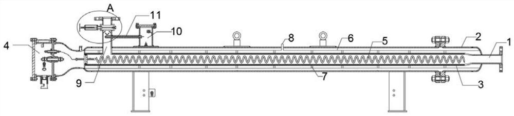
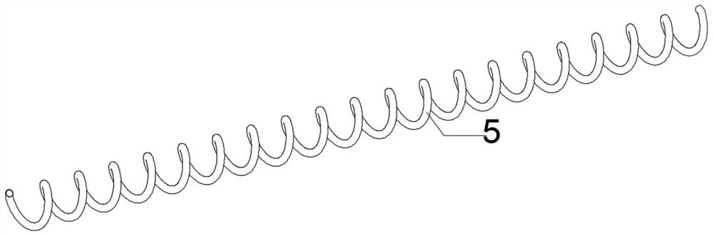
[0024] see Figure 1-3 , this embodiment provides an oil and gas wellhead high-efficiency energy-saving explosion-proof electromagnetic heater, including a liquid inlet pipe 1, an explosion-proof heating shell 2, a heating layer 3, an explosion-proof junction box 4, and a heating tube 5; the inside of the explosion-proof heating shell 2 There is a heating layer 3 for heating the oil, and one end of the heating layer 3 communicates with the liquid inlet pipe 1 for inputting oil; The oil outlet pipe 9 communicates; the heating layer 3 is provided with a heating pipe 5; the heating pipe 5 is a hollow pipe, and the shape of the heating pipe 5 is spring-shaped; The heating strip, and the gap between the heating strip and the inner wall of the heating tube 5 is filled with a heat medium conduction medium; the explosion-proof junction box 4 that is electrically connected to the heating strip and controls the operation of the heating strip is arranged on one side of the explosion-proo...

Embodiment 2

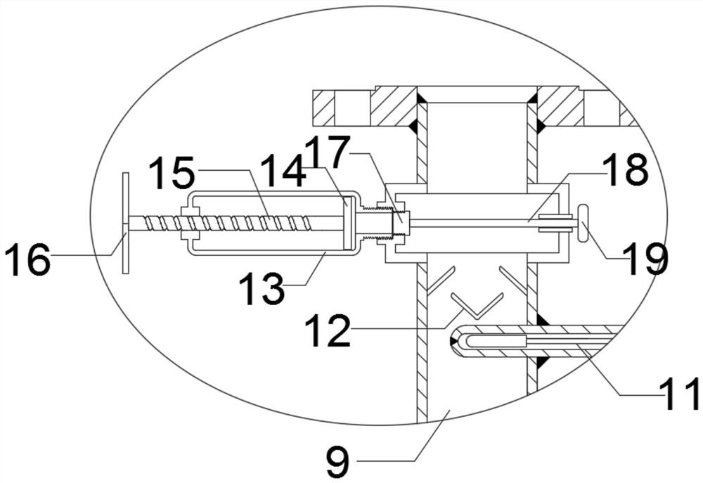
[0033] This embodiment is further improved on the basis of Embodiment 1. The improvements are as follows: in order to facilitate the control of the amount of sampling, the transparent sampling cylinder 13 is provided with a scale; Poorly, the liquid outlet pipe 9 below the transparent sampling cylinder 13 is provided with a plurality of inclined plates 12 for disturbing the oil.

[0034] In order to detect the temperature of petroleum and natural gas in the liquid pipe 9, one side of the explosion-proof heating shell 2 is provided with an external overheating junction box 10, and the outer overheating junction box 10 is provided with an outlet medium temperature measuring thermal resistor 11 for detecting temperature; One end of the outlet medium temperature measuring thermal resistance 11 is arranged in the liquid outlet pipe 9 .


PUM


Abstract

The invention discloses an oil and gas wellhead high-efficiency energy-saving explosion-proof electromagnetic heater, which comprises a liquid inlet pipe, an explosion-proof heating shell, a heating layer, an explosion-proof junction box and a heating pipe; a heating pipe is arranged in the heating layer; the heating pipe is a hollow pipe, And the shape of the heating tube is spring-shaped; the heating tube is provided with a heating strip for heating, and the gap between the heating strip and the inner wall of the heating tube is filled with a heat transfer medium. The oil and gas wellhead high-efficiency energy-saving explosion-proof electromagnetic heater has a spring-shaped heating tube, so the heat exchange area between the oil and the heating tube is large, so that the cold oil will gradually move from the right side of the heating tube to the left side, so that it can The oil is gradually heated, so that the oil discharged from the liquid outlet pipe is heated evenly, and the spring-shaped heating pipe causes the oil in the heating layer to mix during movement, thereby increasing the heating time of the oil and effectively improving the temperature. The heating effect of the device on the oil.

Description

technical field [0001] The invention relates to the technical field of oil and gas explosion-proof and anti-magnetic heating equipment, in particular to an oil and gas wellhead high-efficiency energy-saving explosion-proof electromagnetic heater. Background technique [0002] Petroleum, also called crude oil, is a viscous dark brown liquid fuel extracted from deep underground. During the process of oil extraction and transportation, in order to reduce the viscosity of oil, it is usually necessary to heat the oil. At present, the heating devices for oil are all heated by ordinary electric heating. The pipeline is heated on the outside of the oil transportation pipeline, so as to heat the oil. In this way, the oil on the outside will contact the inner wall of the pipeline. Contact first and be heated first, which will cause uneven temperature inside the oil, which will affect the heating effect to a certain extent. Contents of the invention [0003] The purpose of the prese...

Claims


Application Information

Patent Timeline
Patent Type & Authority Patents(China)
IPC IPC(8): F17D1/18F16L53/34F16L59/02
CPCF16L59/029F17D1/18F16L53/34
Inventor 郑元满
Owner 上海颢柏能源科技有限公司
Why Eureka
Try Eureka