A fence-type bone cement spinal fusion device adopting balloon molding

A fusion device and bone cement technology, applied in the field of intervertebral fusion, can solve the problems of large volume, small production process, single production cost, etc., and achieve the effects of simple device structure, avoidance of use, and reduced volume

Active Publication Date: 2021-06-22
ZHUHAI WEIERKANG BIOTECH
View PDF14 Cites 0 Cited by
  • Summary
  • Abstract
  • Description
  • Claims
  • Application Information

AI Technical Summary

Problems solved by technology

[0005] The purpose of the present invention is to address the deficiencies in the prior art, to provide a fence-type bone cement spinal fusion device using balloon molding, to solve the surgical problems caused by the large or small volume of traditional fusion devices on the market and the single production process. The problem of increased production cost, etc., in order to achieve the above purpose, the present invention is achieved through the following technical solutions

Method used


Image

  • A fence-type bone cement spinal fusion device adopting balloon molding
  • A fence-type bone cement spinal fusion device adopting balloon molding
  • A fence-type bone cement spinal fusion device adopting balloon molding

Examples


Embodiment 1

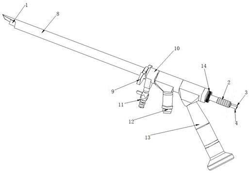
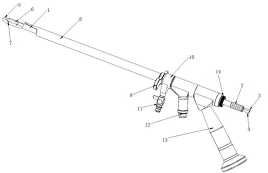
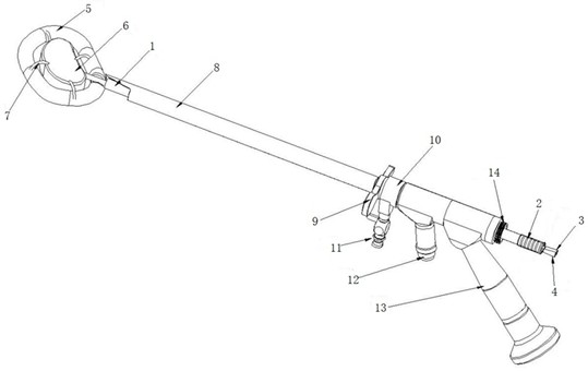
[0029] Such as Figure 1 to Figure 5 As shown, a fence-shaped bone cement spinal fusion device adopting balloon molding includes a balloon system and an endoscope system, and the balloon system adopted in the present invention includes an outer fence-shaped balloon 5 and a central butterfly-shaped balloon 6. Among them, the shape of the outer fence-shaped balloon 5 is irregular oval, the shape of the central butterfly-shaped balloon 5 is irregular butterfly-shaped, and the outer fence-shaped balloon 5 is placed in the central butterfly-shaped ball The outside of the capsule 6 needs to be fixedly connected by 8 balloon connecting bands 7 between the two, so that the two become a fixed balloon device, and finally the outer fence type balloon 5, the central butterfly balloon 6 and the balloon After the balloon connecting band 7 is fixedly connected, the whole scales into the balloon sleeve 1. Through the fixing effect of the balloon connecting band 7, it can effectively prevent t...

Embodiment 2

[0034] Such as Figure 1 to Figure 3As shown, by adopting the spinal fusion device made in the above-mentioned embodiment 1 to implement the intervertebral fusion operation, the balloon system of the present invention, when not in use, the outer fence-shaped balloon 5, the central butterfly-shaped balloon 6 and the balloon After the connecting band 7 is fixedly connected, the whole is zoomed into the balloon sleeve 1, such as figure 1 Shown; After utilizing cannula handle 2 to push forward, the balloon system of the present invention becomes shriveled contraction state, and this moment has not yet inflated, as figure 2 As shown; before the release of the balloon, the balloon can be implanted or explanted between the two vertebral body endplates through the minimally invasive incision through the endoscope system. After the butterfly balloon 6 is inflated, see the state image 3 , can make the two balloons inflate and expand, and then stretch the intervertebral endplate, rai...


PUM


Abstract

A fence-shaped bone cement spinal fusion device adopting balloon molding, including a balloon system and an endoscope system, the outer fence-shaped balloon of the balloon system and the central butterfly-shaped balloon are fixedly connected by a balloon connection belt , the outer fence-shaped balloon, the central butterfly-shaped balloon and the balloon connection belt are fixed and connected as a whole to expand into the balloon sleeve, and the rear ends of the outer fence-shaped balloon and the central butterfly-shaped balloon are designed with independent balloons The inflatable interface, the cannula handle is sleeved on the central butterfly-shaped balloon inflated interface and the outer fence-shaped balloon inflated interface. The endoscope system includes a working sheath and an endoscope. The capsule sleeve is socketed with the instrument channel of the endoscope and the sleeve handle is exposed at the interface of the instrument channel; the invention can effectively reduce the surgical incision and avoid spinal injury caused by applying the external fixation system.

Description

technical field [0001] The invention relates to the technical field of intervertebral fusion, in particular to a fence-type bone cement spinal fusion device formed by a balloon. Background technique [0002] In recent years, the proportion of spinal fusion in surgical operations has steadily increased. Most of the surgical procedures are performed using fusion cages. Specifically, after the fusion cage is embedded and fixed to reach the required intervertebral space, the bone graft is placed in the bone graft cavity. In the past, spinal fusion surgery needed to be completed with a fusion cage and an external fixation system, and the height of the intervertebral space was raised through external support, so as to restore the physiological structure of the spine. [0003] At present, most fusion cages on the market are of fixed size or expandable type. The height of fusion cages is often higher than that of the intervertebral space, and their volume is large. The original spi...

Claims


Application Information

Patent Timeline
Patent Type & Authority Patents(China)
IPC IPC(8): A61F2/46A61B17/88A61B1/317A61B1/12A61B1/07A61B1/018A61B1/015
CPCA61B1/015A61B1/018A61B1/07A61B1/12A61B1/317A61B17/8811A61B17/8819A61B17/8855A61F2/4455A61F2/4611A61F2002/4635
Inventor 范双玲张红导李小雪
Owner ZHUHAI WEIERKANG BIOTECH
Why Eureka
Try Eureka