Automatic rivet feeding die mechanism

A mold mechanism and automatic technology, applied in the field of stamping molds, can solve problems such as easy riveting leakage, low production efficiency, and outflow of defective products

Pending Publication Date: 2021-04-30
SOHBI CRAFT CHANGSHU
View PDF1 Cites 0 Cited by
  • Summary
  • Abstract
  • Description
  • Claims
  • Application Information

AI Technical Summary

Problems solved by technology

In the existing technology, there are usually two processing methods. One is to stamp the metal stamping parts separately first, and then use riveting equipment to rivet and connect the two metal stamping parts. This structure requires multiple procedures to operate , the cost is high, and the production efficiency is low; the other is to adopt the stamping form to rivet and install the rivet parts in the mold. The specific form is: the finished product is punched through the mold with the mold body. The punching device moves down to punch the rivet to the position where the rivet needs to be installed on the product. After punching, the general mold structure requires the operator to manually discharge the rivet and install the rivet to the position where the rivet needs to be installed on the product. , not only consumes manpower and time, but also has low labor efficiency, and the operation is complicated, which is prone to adverse situations such as missing riveting, which affects product quality and production efficiency
[0003] In order to solve the above problems, the existing manufacturers have made many beneficial attempts. The Chinese utility model patent authorization announcement number CN208853624U discloses a "in-mold riveting continuous stamping die", which includes a first riveting punch head, a second Two riveting punching head, material belt, feeding mechanism, base plate, first pushing and positioning mechanism, second pushing and positioning mechanism, second riveting plate, the first pushing and positioning mechanism, second pushing and positioning mechanism, and second riveting plate are respectively installed on the base plate Above, the first pushing and positioning mechanism and the second pushing and positioning mechanism respectively include the first guide block and the first riveting plate, the feeding mechanism is connected with the first guiding block, and the riveting is formed along the feeding mechanism, the first guiding block and the first riveting plate. part passage; the material strip is located directly above the first riveting plate and the second riveting plate, and the first riveting punch and the second riveting punch are respectively located above the material strip; it has the described ability to realize full automation for in-mold continuous Stamping riveting and automatic delivery of riveted parts have the advantages of high precision, high efficiency, high pass rate and good safety, but there are still the following problems: because it is impossible to effectively detect whether the feeding mechanism has delivered all the riveted parts to the products that need to be processed, Moreover, it cannot effectively detect whether the rivets have been installed in place after stamping. After a long period of use, the rivets will be missed, which will lead to the outflow of bad products and directly affect their performance.

Method used


Image

  • Automatic rivet feeding die mechanism
  • Automatic rivet feeding die mechanism
  • Automatic rivet feeding die mechanism

Examples


Embodiment Construction

[0027] In order to understand the technical essence and beneficial effects of the present invention more clearly, the applicant will describe in detail the following examples, but the descriptions of the examples are not intended to limit the solutions of the present invention. Equivalent transformations that are only formal but not substantive should be regarded as the scope of the technical solution of the present invention.

[0028] In the following descriptions, all concepts involving directionality or orientation of up, down, left, right, front and rear are based on figure 1 The current position is a reference, so it cannot be understood as a special limitation on the technical solution provided by the present invention.

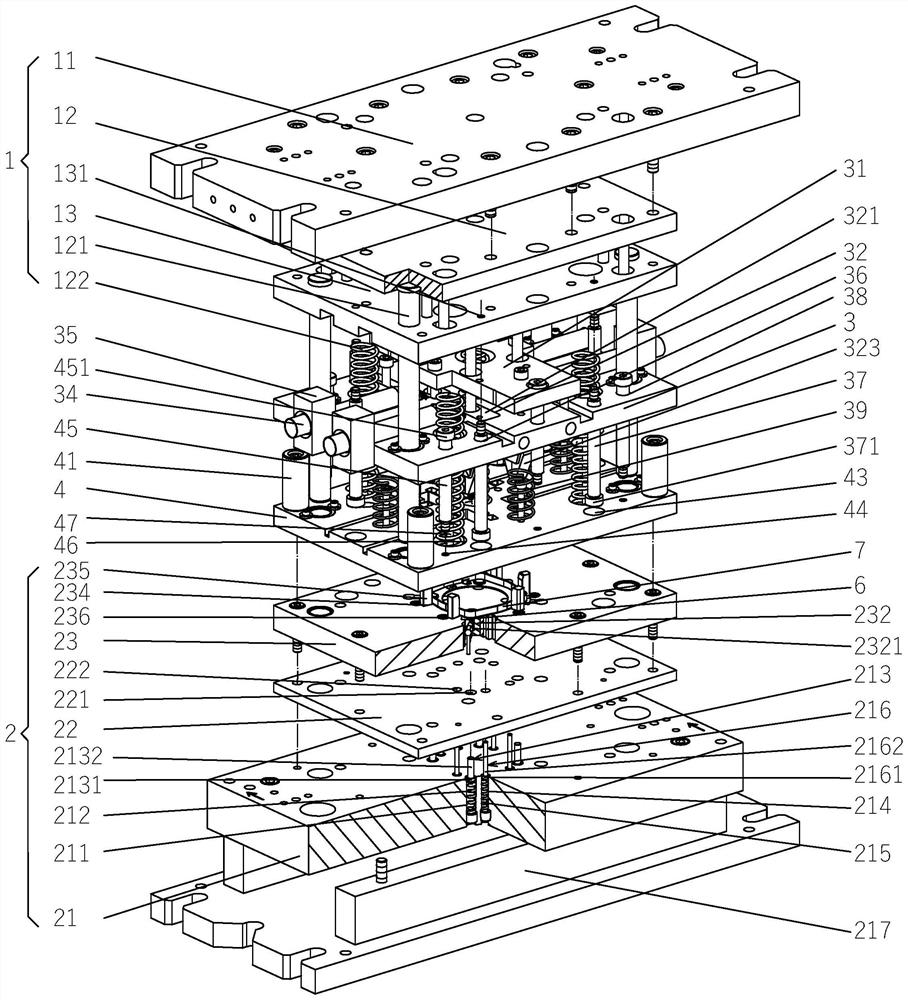
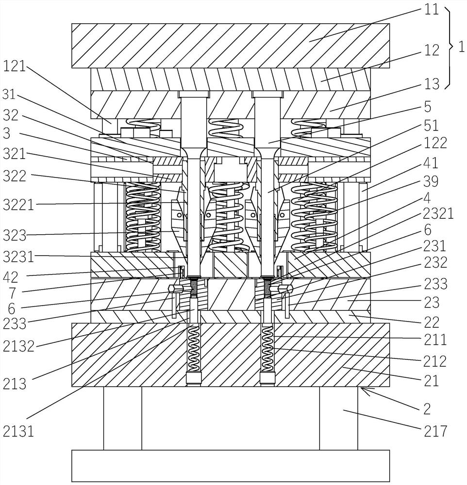
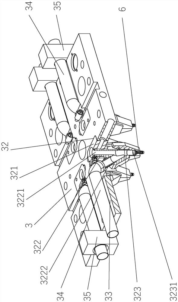
[0029] See Figure 1 to Figure 4 , shows an automatic riveting die mechanism, as the technical gist of the present invention: it includes an upper die assembly 1, a lower die assembly 2, an upper stripping plate 3, a lower stripping plate 4 and several...


PUM


Abstract

An automatic rivet feeding die mechanism comprises an upper die assembly, a lower die assembly, an upper stripper plate, a lower stripper plate and a riveting punch, the upper die assembly comprises an upper die frame plate, an upper die base plate and an upper die fixing plate, the lower die assembly comprises a lower die frame plate, a lower die base plate and a female die plate, the lower stripper plate is arranged on the female die plate, and a stamping rod positioning hole is formed in the upper stripper plate. A stamping rod positioning piece is arranged in the stamping rod positioning hole, a feeding piece is arranged below the stamping rod positioning piece, a feeding piece through hole is formed in the feeding piece, feeding piece grippers are arranged on the two sides of the feeding piece, a feeding channel groove is formed in one side of the upper discharging plate, a feeding guide head is arranged on a body of the feeding piece, a feeding air pipe is arranged in the feeding channel groove, and an annular sensor is arranged on the feeding air pipe. A rivet positioning piece containing groove is formed in the female die plate, a rivet positioning piece is arranged in the containing groove, a rivet stamping hole is formed in the rivet positioning piece, and a rivet detection sensor is arranged in the female die plate. The phenomenon that rivets are missed to be placed is prevented; and after stamping is completed, whether rivets are installed in place or not is detected, the reliability of products is guaranteed, and the production efficiency is improved.

Description

technical field [0001] The invention belongs to the technical field of stamping dies, in particular to an automatic riveting die mechanism. Background technique [0002] At present, in the existing industrial production process, rivets are often used to connect sheet metal parts. Therefore, it is necessary to stamp and install rivets on stamped parts to improve the convenience of connecting with other parts. In the existing technology, there are usually two processing methods. One is to stamp the metal stamping parts separately first, and then use riveting equipment to rivet and connect the two metal stamping parts. This structure requires multiple procedures to operate , the cost is high, and the production efficiency is low; the other is to adopt the stamping form to rivet and install the rivet parts in the mold. The specific form is: the finished product is punched through the mold with the mold body. The punching device moves down to punch the rivet to the position wher...

Claims


Application Information

Patent Timeline
Patent Type & Authority Applications(China)
IPC IPC(8): B21J15/10B21J15/32B21J15/36B21J15/38B21J15/44
CPCB21J15/10B21J15/32B21J15/36B21J15/38B21J15/44
Inventor 林燕沈敏霞顾宇钧杨志军
Owner SOHBI CRAFT CHANGSHU
Why Eureka
Try Eureka