
Buzzer vibration plate perforating device

A vibrating plate and buzzer technology, applied in transportation and packaging, boring/drilling, drilling/drilling equipment, etc., can solve problems such as damage to buzzer components, lower sound transmission quality, and difficult cleaning

Inactive Publication Date: 2021-04-30
新昌县皇骐电子科技有限公司
View PDF6 Cites 1 Cited by
  • Summary
  • Abstract
  • Description
  • Claims
  • Application Information

AI Technical Summary

Problems solved by technology

[0002] The vibrating plate of the buzzer is one of the main components inside the buzzer. The vibration of the vibrating plate makes it produce sound, so as to achieve the effect of alarm, and some buzzers will be carried out on the vibrating plate in order to improve the intensity of sound wave transmission. The special hole treatment can improve the sound wave intensity when the vibrating plate vibrates. However, after the vibrating plate is opened, because the vibrating plate itself is basically made of metal, it is difficult to clean the inside of the groove on the vibrating plate, which makes the vibrating plate There will be accumulation of metal dust in the hole. During normal use, the metal dust on the vibrating plate will spread in the buzzer due to vibration and other factors, which may reduce the quality of sound transmission and cause certain components inside the buzzer. damage, for this reason, we propose a buzzer vibrating plate opening device

Method used


Image

  • Buzzer vibration plate perforating device
  • Buzzer vibration plate perforating device
  • Buzzer vibration plate perforating device

Examples


Embodiment Construction

[0032]The following will clearly and completely describe the technical solutions in the embodiments of the present invention with reference to the accompanying drawings in the embodiments of the present invention. Obviously, the described embodiments are only some, not all, embodiments of the present invention. Based on the embodiments of the present invention, all other embodiments obtained by persons of ordinary skill in the art without making creative efforts belong to the protection scope of the present invention.

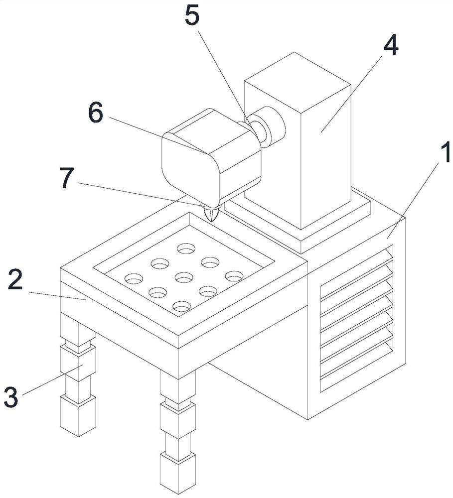
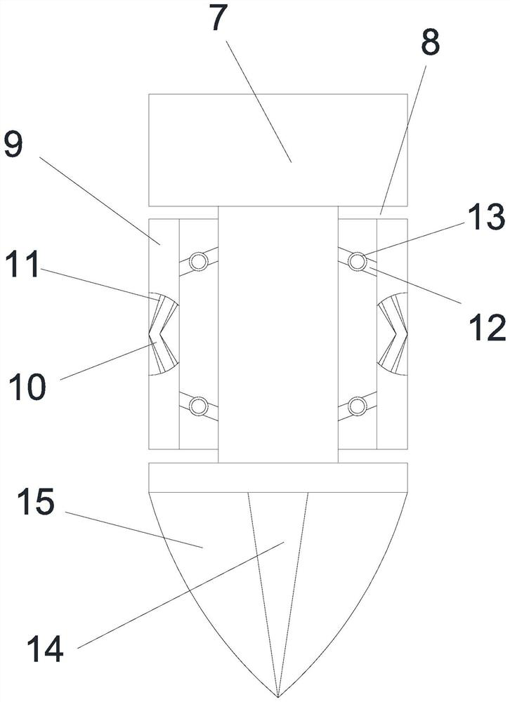
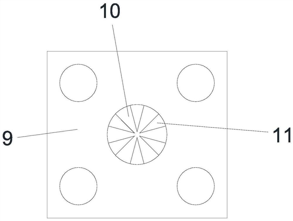
[0033] see Figure 1-Figure 8 , the present invention provides a technical solution: a buzzer vibrating plate opening device, including a base box 1, a table top 2 is fixedly installed on the left side of the base box 1, and support legs are fixedly installed on the front and rear sides of the left end of the bottom of the table top 2 3. The control equipment box 4 is fixedly installed on the top of the base box 1. The inside of the control equipment box 4 is h...


PUM


Abstract

The invention discloses a buzzer vibration plate perforating device, and relates to the field of electronic products. The buzzer vibration plate perforating device comprises a base box, wherein a table top is fixedly installed on the left side of the base box; supporting legs are fixedly installed on the front side and the rear side of the left end of the bottom of the table top; a control equipment box is fixedly installed on the top of the base box; and control equipment is arranged in a hollow area in the control equipment box. According to the buzzer vibration plate perforating device provided by the invention, a sealed rubber plate can be expanded in a slotted hole through inertia generated by rotation of a drill bit, and an adjusting rod in the sealed rubber plate is forced to enable an auxiliary motion block and a main motion block to rub in the sealed rubber plate through the deformation force of the sealed rubber plate and the rotation inertia of the drill bit; and static electricity is attached to a metal cone through conduction of a metal plate and a metal cone, and the metal cone discontinuously makes contact with the inner wall of a groove hole in the vibration plate in cooperation with deformation expansion of the sealed rubber plate, so that the metal powder on the inner walls of the holes in the vibration plate can be effectively adsorbed.

Description

technical field [0001] The invention relates to the field of electronic products, in particular to a hole-opening device for a vibrating plate of a buzzer. Background technique [0002] The vibrating plate of the buzzer is one of the main components inside the buzzer. The vibration of the vibrating plate makes it produce sound, so as to achieve the effect of alarm, and some buzzers will be carried out on the vibrating plate in order to improve the intensity of sound wave transmission. The special hole treatment can improve the sound wave intensity when the vibrating plate vibrates. However, after the vibrating plate is opened, because the vibrating plate itself is basically made of metal, it is difficult to clean the inside of the groove on the vibrating plate, which makes the vibrating plate There will be accumulation of metal dust in the hole. During normal use, the metal dust on the vibrating plate will spread in the buzzer due to vibration and other factors, which may re...

Claims


Application Information

Patent Timeline
Patent Type & Authority Applications(China)
IPC IPC(8): B23B41/00B23B51/00B23Q11/00
CPCB23B41/00B23B51/00B23Q11/0042B23Q11/0064
Inventor 谢军红
Owner 新昌县皇骐电子科技有限公司
Learn More