
Mortise and tenon type machine frame used for liquid rocket engine

A liquid rocket and engine technology, applied in the field of tenon-and-mortise frame, can solve the problems of reducing fatigue strength, reducing bearing capacity, stress concentration at welded joints, etc., and achieving the effects of improving quality, small deformation and increasing reliability

Pending Publication Date: 2021-04-30
北京中科宇航技术有限公司
View PDF0 Cites 2 Cited by
  • Summary
  • Abstract
  • Description
  • Claims
  • Application Information

AI Technical Summary

Problems solved by technology

[0003] In the prior art, the rocket engine frame is generally a truss structure or a truss structure. The truss structure or truss structure is manufactured through welding operations. The size of the frame is relatively large, and large positioning tooling is required during welding, and the load-bearing beams and connections during the welding process The beams of the load-bearing beams will have a large deformation, which requires very high welding skills of the welders. Due to the different welding skills of the welders, the quality of the welding is difficult to guarantee; and the welding joints are easy to cause Stress concentration, lower bearing capacity, lower fatigue strength

Method used


Image

  • Mortise and tenon type machine frame used for liquid rocket engine
  • Mortise and tenon type machine frame used for liquid rocket engine
  • Mortise and tenon type machine frame used for liquid rocket engine

Examples


Embodiment

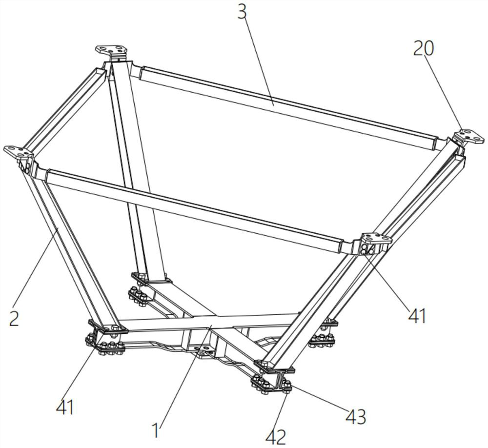
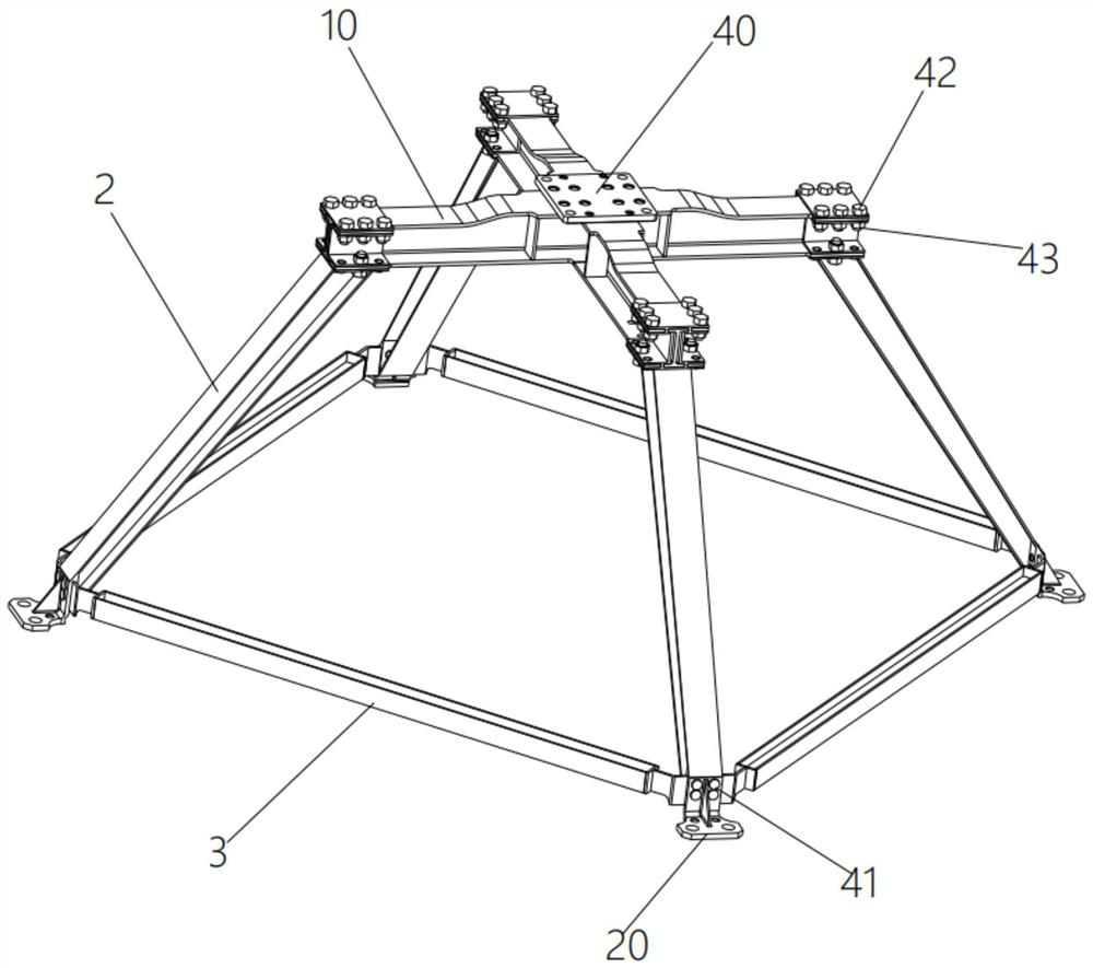
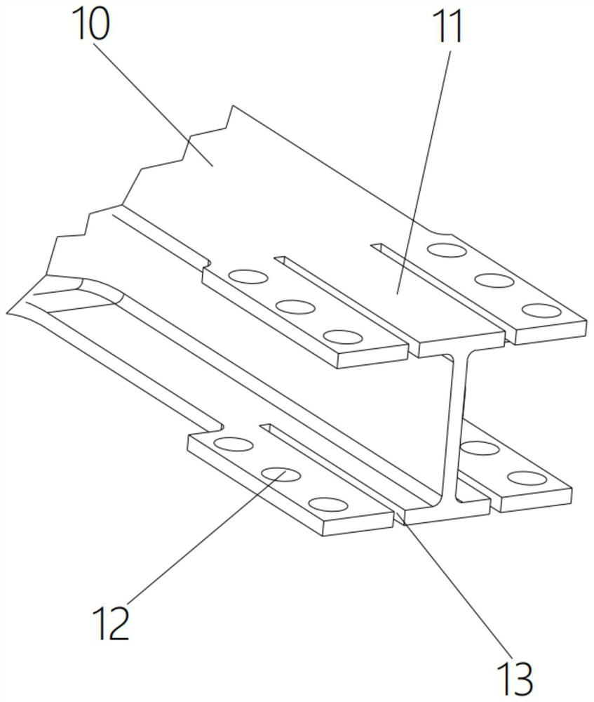
[0031] Such as Figure 1-6 As shown, the present invention discloses a mortise and tenon frame for a liquid rocket engine, comprising a cross beam 1, a load-bearing beam 2 and a cross beam 3, the cross-sections of the cross beam 1, load-bearing beam 2 and cross beam 3 are I-shaped, with mortise and tenon plugs 11 at the four ends of the cross beam 1, the number of bearing beams 2 is four, and the lower end of each bearing beam 2 is provided with a mortise and tenon joint that fits with the mortise and tenon plugs 11 The socket 21, through the insertion of the mortise and tenon plug 11 and the tenon and tenon socket 21, inserts and fixes the four load-bearing beams 2 on the four ends of the cross beam 1 respectively, and two Mortise and tenon slots 25, two mortise and tenon slots 25 are arranged on both sides of the upper end of the load-bearing beam 2, the number of beams 3 is four, and the four beams 3 are respectively arranged between every two adjacent load-bearing beams 2,...


PUM


Abstract

The invention discloses a mortise and tenon type machine frame used for a liquid rocket engine. The mortise and tenon type machine frame used for the liquid rocket engine comprises a cross-shaped beam, force bearing beams and cross beams, mortise and tenon plugs are arranged at four ends of the cross-shaped beam; the number of the force bearing beams is four, the lower ends of the force bearing beams are provided with mortise and tenon sockets which are inserted into the mortise and tenon plugs, the upper ends of the force bearing beams are provided with two mortise and tenon insertion grooves; and the number of the cross beams is four, the cross beams are arranged between every two adjacent force bearing beams, and the two ends of each cross beam are each provided with a mortise and tenon insertion piece inserted into the corresponding mortise and tenon insertion groove. The four force bearing beams are inserted and fixed to the four ends of the cross-shaped beam respectively through insertion of the mortise and tenon plugs and the mortise and tenon sockets, the four cross beams are inserted and fixed between every two adjacent force bearing beams respectively through insertion of the mortise and tenon insertion pieces and the mortise and tenon insertion grooves, and therefore assembly of the cross-shaped beam, the force bearing beams and the cross beams is achieved, and the whole machine frame is formed, the welding steps are reduced, the deformation of the machine frame is small, the machining quality is improved, meanwhile, stress concentration does not occur, and the reliability of the machine frame in the using process can be improved.

Description

technical field [0001] The invention belongs to the technical field of rocket engine racks, in particular to a mortise and tenon rack for liquid rocket engines. Background technique [0002] As an important force transmission mechanism, the rocket engine rack is generally composed of various beams. The structural design should meet the requirements of compact geometric size, lightest structural mass, uniform stress distribution and sufficient structural rigidity. Under constraints, the axial and radial stiffness of the rocket and the fulcrum stiffness of the servo actuator are guaranteed to the maximum extent. [0003] In the prior art, the frame of the rocket engine is generally a truss structure or a truss structure. The truss structure or truss structure is manufactured through welding operations. The size of the frame is relatively large, and large positioning tooling is required during welding, and the load-bearing beams and connections during the welding process The b...

Claims


Application Information

Patent Timeline
Patent Type & Authority Applications(China)
IPC IPC(8): F02K9/60F16B7/18F16B7/20F16B7/00
CPCF02K9/60F16B7/18F16B7/185F16B7/20F16B7/00
Inventor 不公告发明人
Owner 北京中科宇航技术有限公司
Learn More