
Welded whole moving oil cylinder structure of injection molding machine

A kind of technology of shifting oil cylinder and welding, applied in the direction of fluid pressure actuating device, etc., can solve the problems of oil leakage of end cover cylinder, large parallelism of end cover, error and so on

Pending Publication Date: 2021-04-30
浙江泰瑞重型机械有限公司
View PDF0 Cites 0 Cited by
  • Summary
  • Abstract
  • Description
  • Claims
  • Application Information

AI Technical Summary

Problems solved by technology

When the pretightening force of the four long bolts is inconsistent, there will be a large parallelism error between the two end covers, which may eventually cause a gap between the end cover and the cylinder, resulting in hydraulic oil leakage
[0003] Four long bolts tie-rod hydraulic cylinders require four long bolts to compress the two cylinder end covers and cylinder barrels during assembly. When the cylinder is working, the four long bolts are affected by cyclic stress loads at the same time, and fatigue damage is prone to occur after long-term work. , resulting in oil leakage between the end cover cylinder

Method used


Image

  • Welded whole moving oil cylinder structure of injection molding machine
  • Welded whole moving oil cylinder structure of injection molding machine
  • Welded whole moving oil cylinder structure of injection molding machine

Examples


Embodiment Construction

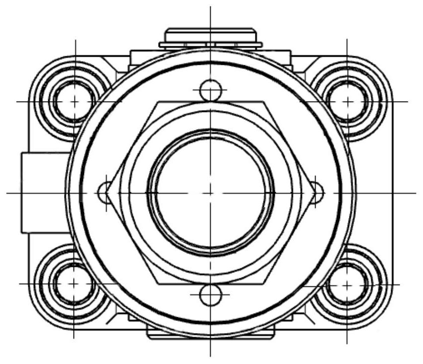
[0029] An embodiment of the present invention provides a structure of a welding-type shifting oil cylinder for an injection molding machine.

[0030] The device structure of the present invention will be described in detail below with reference to the accompanying drawings. Apparently, the embodiments described below only include a part of the embodiments of the present invention, rather than all of them. Based on the embodiments of the present invention, all other embodiments obtained by persons of ordinary skill in the art without making creative efforts fall within the protection scope of the present invention.

[0031] The structure of a welded full-movement oil cylinder for an injection molding machine provided by the present invention is as follows: Figure 1 ~ Figure 4 shown. The structure includes a bolt 1, a shifting cylinder hanging pin 2, a shifting joint pin 3, a shifting front joint 4, a second nut 5, a shifting cylinder bottom 6, a shifting piston 7, a shifting ...


PUM


Abstract

The invention discloses a welded whole moving oil cylinder structure of an injection molding machine. a whole moving oil cylinder hitching leg is connected with a whole moving front connector through a whole moving connector pin, and an elastic check ring for a shaft is further arranged at the connection position of the whole moving connector pin; the whole moving front connector is in threaded connection with the whole moving cylinder bottom; an L-shaped hydraulic oil inlet and outlet channel is formed in the whole moving cylinder bottom, and the whole moving cylinder bottom is welded with a whole moving cylinder barrel; a whole moving guide sleeve is arranged in the whole moving cylinder barrel, and installed on the side opposite to the whole moving cylinder bottom; the whole moving guide sleeve is in threaded connection with the whole moving cylinder barrel, and a first O-type sealing ring is arranged at the connection position between the whole moving guide sleeve and the whole moving cylinder barrel; a whole moving piston is arranged on one side of the inner cylinder bottom of the whole moving cylinder barrel, and a whole moving piston rod is in threaded connection with the whole moving piston; the whole moving piston rod penetrates through the whole moving guide sleeve, and extends out of the whole moving cylinder barrel; two glyd rings are arranged between the whole moving piston and the whole moving cylinder barrel for double-acting sealing, and a second wearing ring is further arranged; and a U-type sealing ring, a first wearing ring and a second O-type sealing ring are arranged between the whole moving guide sleeve and the whole moving piston rod.

Description

【Technical field】 [0001] The invention relates to the technical field of injection molding machine equipment, and in particular relates to a structure of a welding-type translational oil cylinder for an injection molding machine. 【Background technique】 [0002] At present, the mobile oil cylinder of the injection seat of the injection molding machine generally adopts a long bolt tie rod type hydraulic oil cylinder, and four long bolt tie rods press the front and rear end covers of the hydraulic cylinder tightly on both sides of the cylinder barrel. When the pretightening force of the four long bolts is inconsistent, there will be a large parallelism error between the two end covers, which may eventually lead to a gap between the end cover and the cylinder, resulting in hydraulic oil leakage. [0003] Four long bolts tie-rod hydraulic cylinders require four long bolts to compress the two cylinder end covers and cylinder barrels during assembly. When the cylinder is working, t...

Claims


Application Information

Patent Timeline
IPC IPC(8): F15B15/17F15B15/20B29C45/17
CPCB29C45/17B29C2045/1784F15B15/1423F15B15/1438F15B15/1461F15B15/17
Inventor 郑建国朱金柏谢鹏程张鹏王新峰金焕君孙君陈园方沉稳苏佳
Owner 浙江泰瑞重型机械有限公司
Learn More