Supercharge Your Innovation With Domain-Expert AI Agents!

Deep rock sampling device for geological exploration

A rock sampling and geological exploration technology, applied in the field of deep rock sampling, can solve the problems of severe vibration of sampling device, wear of sampling drill bit, unstable sampling process, etc.

Inactive Publication Date: 2021-04-30
保定理工学院
View PDF0 Cites 0 Cited by
  • Summary
  • Abstract
  • Description
  • Claims
  • Application Information

AI Technical Summary

Problems solved by technology

[0003] The existing rock sampling device for geological exploration has an unstable sampling process when sampling deep rocks, which easily causes severe vibration of the entire sampling device, and at the same time, the wear of the sampling drill bit is relatively serious, which affects the service life of the sampling device

Method used


Image

  • Deep rock sampling device for geological exploration
  • Deep rock sampling device for geological exploration
  • Deep rock sampling device for geological exploration

Examples


Embodiment 1

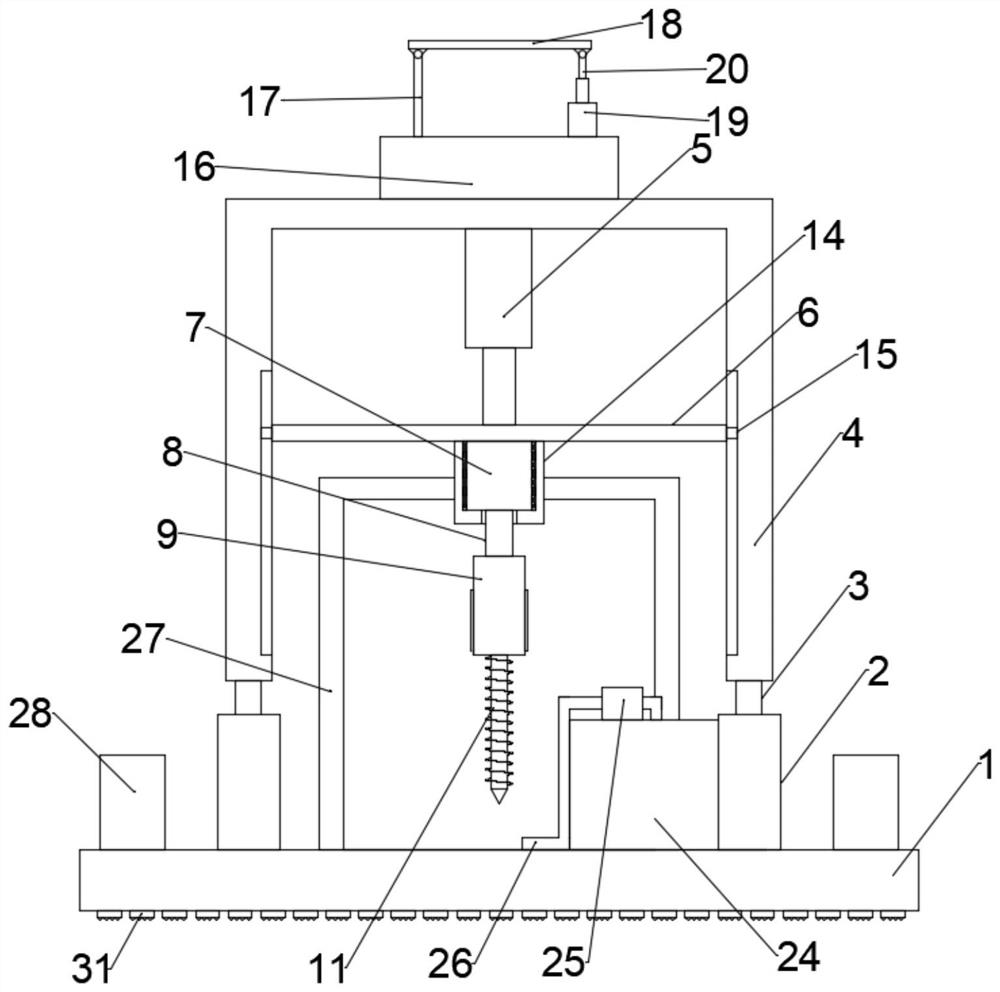
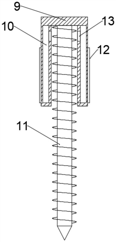
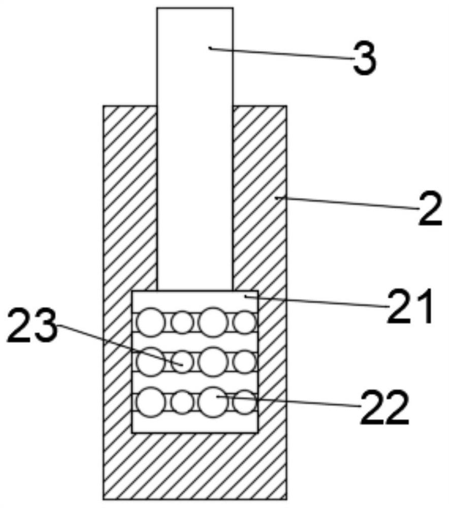
[0025] combine Figure 1-5 , a deep rock sampling device for geological exploration, including a base 1, a plurality of sleeves 2 are fixed on the upper end of the base 1, and a moving rod 3 is slidably connected to the upper ends of the plurality of sleeves 2, and the moving rod 3 and the sleeve 2 is provided with a shock absorbing mechanism, the upper end of the moving rod 3 is fixed with a 匚-shaped mounting frame 4, and the upper end of the inner side of the 匚-shaped mounting frame 4 is installed with a first electric push rod 5, the first The movable end of the electric push rod 5 is connected with a mounting plate 6, and the two ends of the mounting plate 6 are fixed with a slide block 15, and the inner walls of both sides of the 匚-shaped mounting frame 4 are provided with chute, and the slide block 15 and The chute is slidingly connected, the lower end of the mounting plate 6 is fixed with a motor 7, the output end of the motor 7 is equipped with a rotating shaft 8, the ...

Embodiment 2

[0038] combine figure 1 with Figure 4 , a deep rock sampling device for geological exploration, this embodiment further limits the present invention on the basis of embodiment 1.

[0039] A plurality of fixed frames 28 are installed on the upper end of the base 1, a third electric push rod 29 is installed in the plurality of fixed frames 28, and the movable ends of the third electric push rod 29 are connected with universal wheels 30, A through hole is opened on the base 1 and located at the universal wheel 30 , and a push rod 27 is fixed on the upper end of the base 1 .

[0040] Specifically, the universal wheel 30 is adjusted to the bottom of the base 1 through the third electric push rod 29, and is in contact with the ground, and the universal wheel 30 is used to realize the flexible movement of the device through the hand push rod 27. After moving to the sampling site, the The universal wheel 30 is adjusted to the inside of the base 1 through the third electric push rod...


PUM


Abstract

The invention relates to the technical field of deep rock sampling, and particularly discloses a deep rock sampling device for geological exploration, wherein the deep rock sampling device comprises a base, a plurality of sleeves are fixed at the upper end of the base, moving rods are slidably connected to the upper ends of the plurality of sleeves, and damping mechanisms are arranged between the moving rods and the sleeves; a C-shaped mounting frame is fixed to the upper ends of the moving rods, a first electric push rod is mounted at the upper end of the inner side of the C-shaped mounting frame, a mounting plate is connected to the movable end of the first electric push rod, sliding blocks are fixed to the two ends of the mounting plate, sliding grooves are formed in the inner walls of the two sides of the C-shaped mounting frame, and the sliding blocks are slidably connected with the sliding grooves; and a motor is fixed to the lower end of the mounting plate, and a rotating shaft is mounted at the output end of the motor. According to the rock deep sampling device, the defects that an existing rock deep sampling device is unstable in the sampling process, the service life of the sampling device is short and the like can be overcome.

Description

technical field [0001] The invention relates to the technical field of deep rock sampling, in particular to a deep rock sampling device for geological exploration. Background technique [0002] Geological prospecting is the investigation and research activities of conducting geological exploration and detection through various means and methods, determining the appropriate bearing layer, determining the foundation type and calculating the foundation parameters according to the foundation bearing capacity of the bearing layer. To find out the existing mineral deposits of industrial significance, in order to ascertain the quality of the minerals, as well as the technical conditions for mining and utilization, provide the mineral reserves and geological data required for the design of mine construction, and analyze the rocks, strata, structures, minerals, hydrology, and geomorphology of a certain area Conduct survey and research work on geological conditions. [0003] The exis...

Claims


Application Information

Patent Timeline
Patent Type & Authority Applications(China)
IPC IPC(8): G01N1/08
CPCG01N1/08
Inventor 郑娇娇张卓彤胡立新
Owner 保定理工学院
Features
  • R&D
  • Intellectual Property
  • Life Sciences
  • Materials
  • Tech Scout
  • Unparalleled Data Quality
  • Higher Quality Content
  • 60% Fewer Hallucinations
Learn More