Optical cable

An optical cable and optical fiber technology, applied in optical cable. It can solve problems such as low efficiency of optical cable laying

Active Publication Date: 2021-04-30
HUAWEI TECH CO LTD
View PDF11 Cites 3 Cited by
  • Summary
  • Abstract
  • Description
  • Claims
  • Application Information

AI Technical Summary

Problems solved by technology

[0004]It can be seen that in the laying of optical cables, the optical cables need to be replaced frequently, resulting in the problem of low efficiency of optical cable laying

Method used


Image

  • Optical cable
  • Optical cable
  • Optical cable

Examples


Embodiment Construction

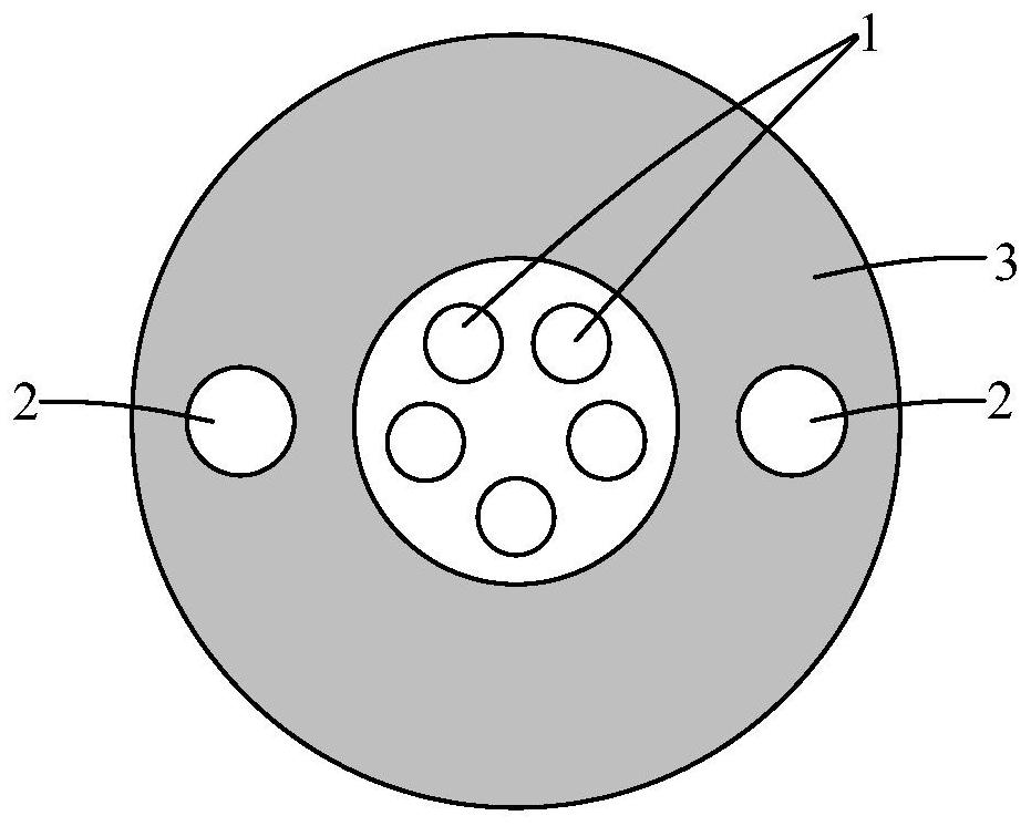
[0059] like figure 1 As shown, the optical cable may include an optical fiber 1 , at least one reinforcing rod 2 and an outer sheath 3 , and both the optical fiber 1 and the at least one reinforcing rod 2 are located in the outer sheath 3 .

[0060] The reinforcing rod 2 mostly uses steel wire or glass fiber reinforced plastic (GFRP, Glass Fiber-Reinforced Plastic). Among them, the steel wire is used as the reinforcing rod of the optical cable. The Young's modulus of the steel wire is relatively high, which makes the optical cable have better tensile elasticity. It is used in overhead laying and can resist a certain tensile stress. However, optical cables with steel wires are easy to bend and difficult to straighten after bending, so they are not easy to pass through pipes when they are used in pipe laying, and pipe threaders are needed.

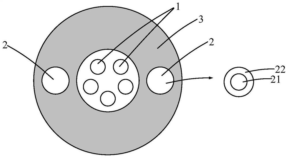
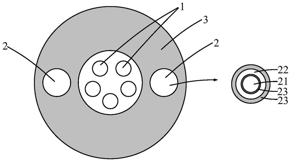
[0061] Glass fiber reinforced plastic is used as the reinforcing rod of the optical cable. Glass fiber reinforced plastic can be bent, and...


PUM

PropertyMeasurementUnit
breaking strengthaaaaaaaaaa
tensile strengthaaaaaaaaaa

Abstract

The invention discloses an optical cable, and belongs to the technical field of optical cable laying. The optical cable comprises an optical fiber, at least one reinforcing rod and an outer sheath, wherein the optical fiber and the at least one reinforcing rod are located in the outer sheath; the Young modulus of the reinforcing rod is greater than 53 GPa, the bending radius of the reinforcing rod is less than 26 D, the straightness returning degree of the reinforcing rod is greater than 80%, the straightness returning degree is the degree that the reinforcing rod returns to a straight rod after being bent, and D is the diameter of the reinforcing rod. With the adoption of the application, the reinforcing rod with the mechanical property is used as a reinforcing piece of the optical cable, so that the optical cable has good tensile elasticity and good bending resilience, so that the optical cable can be applied to overhead laying and can also be applied to pipeline laying. Therefore, in optical cable laying, especially in an alternating laying mode of overhead laying and pipeline laying, the optical cable does not need to be replaced, the optical cable laying time can be saved, and the optical cable laying efficiency is improved.

Description

technical field [0001] The present application relates to the technical field of optical cable laying, in particular to an optical cable. Background technique [0002] With the rapid development of an optical distribution network (ODN), optical cables are more and more widely used. [0003] Optical cable laying methods mainly include aerial laying and pipe laying, and in most scenarios, aerial laying and pipe laying are mixed. Then, in the laying of optical cables, when encountering the need to use overhead laying methods for laying optical cables, technicians need to replace them with optical cables suitable for overhead laying, and when encountering the need to use pipeline laying methods for laying optical cables, technicians need to replace them with Fiber optic cable suitable for duct laying. [0004] It can be seen that in the laying of the optical cable, the optical cable needs to be replaced frequently, which causes the problem of low efficiency of the laying of th...

Claims


Application Information

Patent Timeline
Patent Type & Authority Applications(China)
IPC IPC(8): G02B6/44
CPCG02B6/4433
Inventor 张金星马婧玮李媛媛
Owner HUAWEI TECH CO LTD
Why Eureka
Try Eureka