Electric connector

An electrical connector and electrical connection technology, which is applied in the direction of connection, parts and circuits of connection devices, can solve the problems of increasing design difficulty, increasing processing cost, and easy shaking, so as to reduce the number of terminal assemblies, prevent collision interference, The effect of improving electrical properties

Active Publication Date: 2021-04-30
DEYI PRECISION ELECTRONIC IND CO LTD PANYU
View PDF10 Cites 1 Cited by
  • Summary
  • Abstract
  • Description
  • Claims
  • Application Information

AI Technical Summary

Problems solved by technology

[0002] The existing USB3.1 electrical connector has a row of first terminal groups and a row of second terminal groups, the first terminal group is provided with four terminals, and the second terminal group is provided with five terminals. Both the first terminal group and the second terminal group are punched out from the same strip and injection-molded together in the insulating body. At this time, when viewed along the vertical direction of the board surface of the strip, each terminal of the first terminal group and the second terminal The terminals of the group do not overlap, and the total width formed by the arrangement of the first terminal group and the second terminal group is limited by the standard protocol of the USB connector. The gap between the terminals is small, and the design space of the corresponding terminals is small. , when the USB3.1 electrical connector has crosstalk or impedance mismatch, it is difficult to improve the crosstalk and impedance by changing the shape of each terminal of the first terminal group and each terminal of the second terminal group, and usually requires additional grounding components, increasing design difficulty and increasing processing costs
[0003] Or in the molding process, the five terminals of the second terminal group are all punched out from the same material strip and injection-molded together in the insulating body, and the four terminals of the first terminal group are all punched out from another material strip and assembled together in the insulating body. In the insulating body, although the design space of each terminal is relatively large at this time, since the four terminals of the first terminal group and the five terminals of the second terminal group are punched out of different strips, material waste is caused and processing costs are increased , and during assembly, the four terminals of the first terminal group are easy to shake, and it is difficult to align and assemble the four terminals to the insulating body at the same time, which makes the assembly difficult, reduces the product qualification rate, and affects production efficiency

Method used


Image

  • Electric connector
  • Electric connector
  • Electric connector

Examples


Embodiment 1

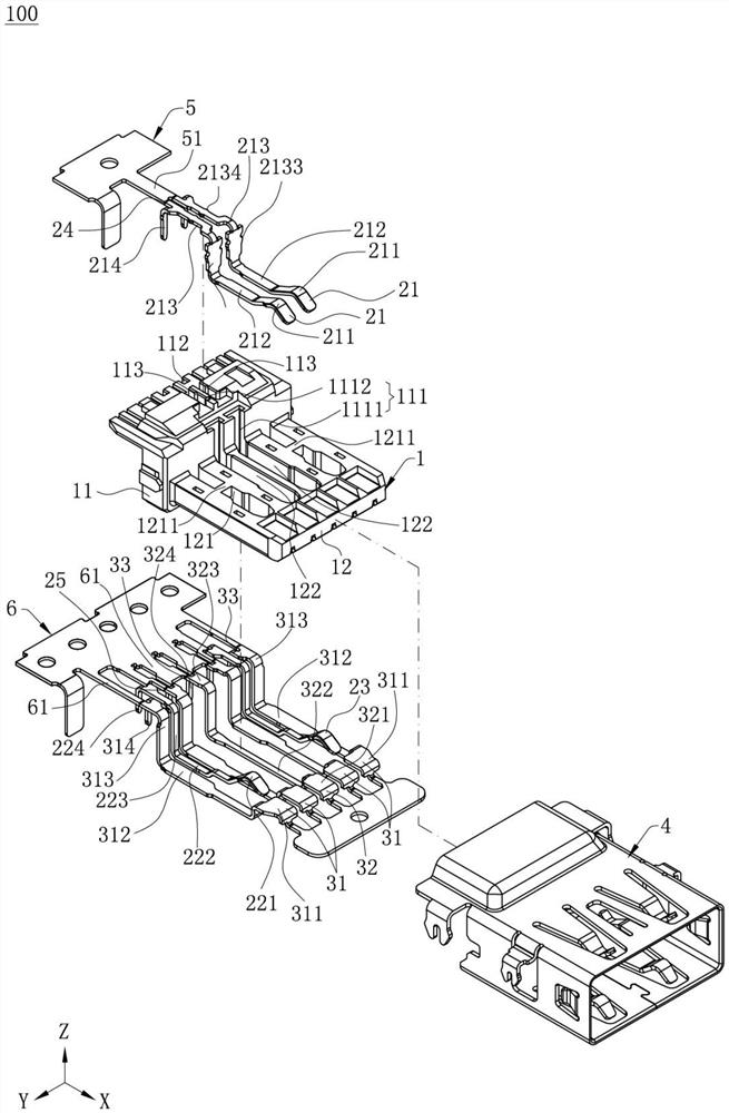
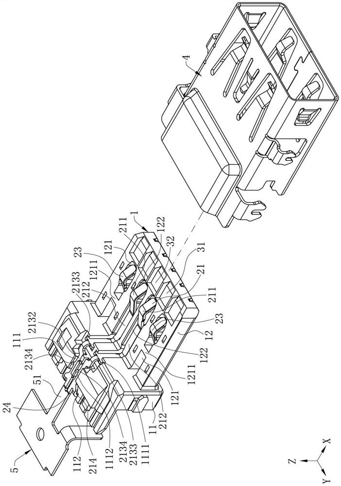
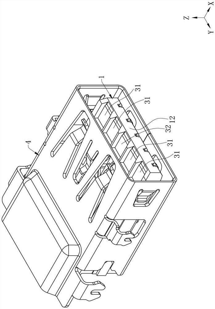
[0041] Such as Figure 1 to Figure 3 As shown, the electrical connector 100 of the present invention is used to dock with a docking connector (not shown) forward. In this embodiment, the electrical connector 100 is a USB 3.1 connector. Of course, in other embodiments, the The electrical connector 100 may also be other connectors for transmitting high-frequency signals. For the convenience of description, the direction in which the electrical connector 100 is docked with the butt connector is set as the front-rear direction, wherein the X-axis is the front-rear direction, the arrow direction of the X-axis is the forward direction, the Y-axis is the left-right direction, and the Y-axis is the left-right direction. The arrow direction of the axis is the right direction, the Z axis is the up and down direction, and the arrow direction of the Z axis is the upward direction.

[0042] Such as Figure 1 to Figure 3 As shown, the electrical connector 100 includes an insulating body 1...

Embodiment 2

[0058] Such as Figure 9 to Figure 12 As shown, in this embodiment, the structure of the electrical connector 100 is basically the same as the structure of the electrical connector 100 in Embodiment 1, the difference is that the second ground connection part 3232 and the differential connection part 3132 are located On the same plane, part of the first ground connection part 2232 and part of the power supply connection part are located on the same plane as the signal connection part 2132 and are located on a different plane from the second ground connection part 3232 and the differential connection part 3132 , under the premise that the first ground connection part 2232, the power supply connection part, the second ground connection part 3232, and the differential connection part 3132 are co-injection-molded on the insulating body 1, the first ground connection part 2232 is located on the same plane as the signal connection part 2132, so that the interference signal of the sig...


PUM


Abstract

The invention discloses an electric connector which comprises a first terminal set, a second terminal set and an insulating body, wherein the first terminal set comprises a first grounding terminal and a signal terminal; the second terminal set comprises a second ground terminal and a differential terminal; and the first grounding terminal, the second grounding terminal and the differential terminal are embedded and molded into a whole with the insulating body, so that a first grounding embedding part of the first grounding terminal, a second grounding embedding part of the second grounding terminal and a differential embedding part of the differential terminal are embedded in the insulating body, and a signal inserting part of the signal terminal is correspondingly assembled in an assembling groove of the insulating body, so that the signal terminal and the differential terminal have large design adjusting spaces, and the structures and the assembling positions of the signal terminal and the differential terminal can be adjusted according to actual signal transmission requirements. Therefore, the position relation of the signal terminal and the differential terminal relative to other terminals is adjusted, impedance is flexibly adjusted, crosstalk is reduced, the electrical performance of the first terminal group and the second terminal group is improved, and installation is convenient at the same time.

Description

【Technical field】 [0001] The invention relates to an electrical connector, in particular to an electrical connector for transmitting high-frequency signals. 【Background technique】 [0002] The existing USB3.1 electrical connector has a row of first terminal groups and a row of second terminal groups, the first terminal group is provided with four terminals, and the second terminal group is provided with five terminals. Both the first terminal group and the second terminal group are punched out from the same strip and injection-molded together in the insulating body. At this time, when viewed along the vertical direction of the board surface of the strip, each terminal of the first terminal group and the second terminal The terminals of the group do not overlap, and the total width formed by the arrangement of the first terminal group and the second terminal group is limited by the standard protocol of the USB connector. The gap between the terminals is small, and the design ...

Claims


Application Information

Patent Timeline
Patent Type & Authority Applications(China)
IPC IPC(8): H01R13/10H01R13/405
CPCH01R13/405H01R13/10Y02T90/14
Inventor 何旭辉
Owner DEYI PRECISION ELECTRONIC IND CO LTD PANYU
Why Eureka
Try Eureka