Motor stator marking device with tracing function

A motor stator and marking device technology, which is applied in electromechanical devices, manufacturing motor generators, manufacturing stator/rotor bodies, etc., can solve problems affecting production, affecting stator electrical performance, scratches, etc.

Inactive Publication Date: 2021-04-30
咸宁恒舟信息科技有限公司
View PDF0 Cites 0 Cited by
  • Summary
  • Abstract
  • Description
  • Claims
  • Application Information

AI Technical Summary

Problems solved by technology

[0002] The rotor and stator are important parts of the motor, and the production process of the stator includes slotting the bottom of the iron core, upper main winding, upper insulating paper, upper auxiliary winding, preliminary shaping, terminal installation, wire binding, reshaping, performance testing and Appearance inspection: At present, the main winding or auxiliary winding on the stator is generally equipped with wire groups embedded in the stator core, but during the upper winding process, there are wire damages on the enameled wire (partial outer paint peeling or scratching, etc.), and the wire damage will affect The electrical performance of the stator; at present, the upper winding is generally equipped with multiple devices; when a wire damage is detected on the stator, it is necessary to stop all the upper winding equipment for inspection, check which equipment has a problem, and avoid the continuous occurrence of wire damage on the stator ; But the shutdown of the upper winding equipment will affect the production; a structure with traceability function is needed, which can quickly determine which upper winding equipment has a problem, and there is no need to stop all equipment sets for inspection

Method used


Image

  • Motor stator marking device with tracing function
  • Motor stator marking device with tracing function
  • Motor stator marking device with tracing function

Examples


Embodiment

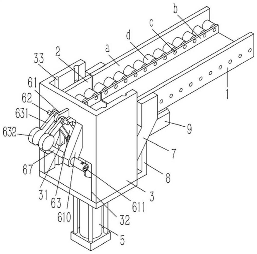
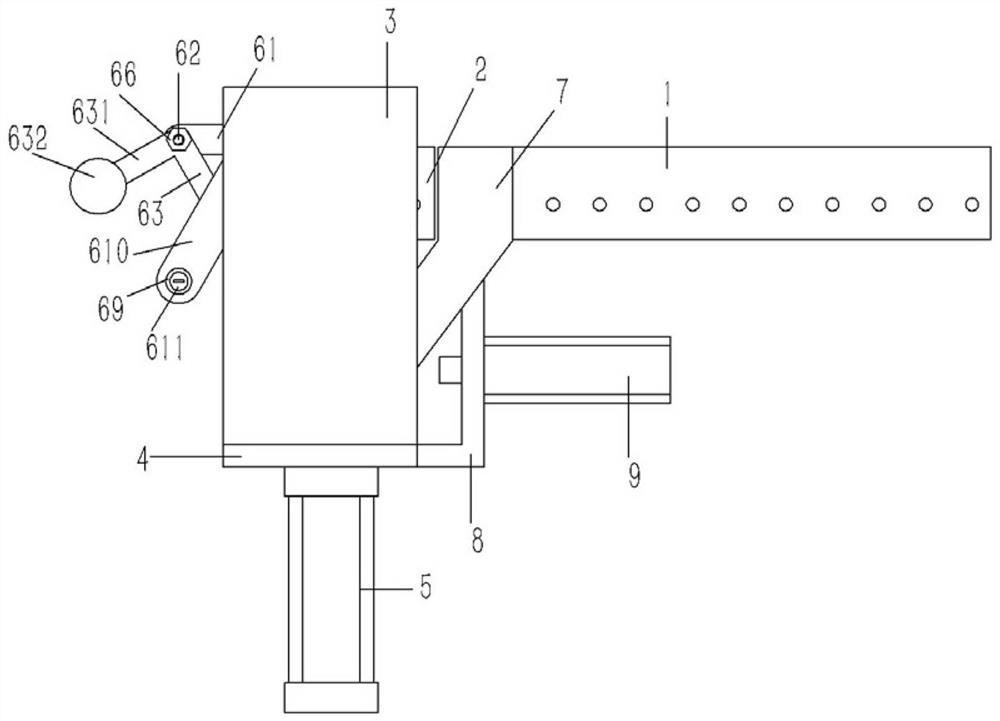
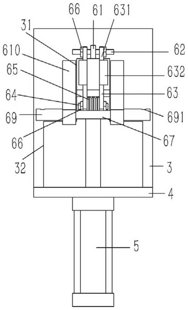
[0022]Example: SeeFigure 1 to 4As shown, a lifting slot rail 2 having a traceable function motor stator marker device, including a horizontal discharge rail 1, and an assembly tank rail 1, a lifting tank 2 inserted in a frame 3 of the "匚" glyph 3, The bottom plate 4 is fixed to the lower end surface of the frame 3, and the vertical lifting cylinder 5 is fixed to the bottom plate 4, and the piston rod of the lifting cylinder 5 is fixed to the lifting slot rail 2; the frame 3 offs from the discharge rail One side of the 1 side, the frame 3 is formed with a slot 31 opposite to the marking mechanism 6, and the lower end of the frame 3 is formed with the discharge port 32 in communication with the slot 31, below the discharge groove rail 1. A push cylinder 9 is provided with the discharge port 32, the pusher cylinder 9 is fixed to the cylinder bracket 8, and the cylinder bracket 8 is fixed to the bottom plate 4;

[0023]The labeling mechanism 6 includes an ear seat 61 fixed to the frame 3, ...


PUM


Abstract

The invention discloses a motor stator marking device with a tracing function, and the device comprises a horizontal discharge grooved rail and a lifting grooved rail at one end of the discharge grooved rail, the lifting grooved rail is inserted into a [-shaped frame, a bottom plate is fixed on the lower end surface of the frame, and a vertical lifting air cylinder is fixed on the bottom plate; a piston rod of the lifting air cylinder penetrates through the bottom plate and is fixed on the lifting grooved rail; a marking mechanism is arranged on the side, deviating from the discharge grooved rail, of the frame, an inserting groove opposite to a marking mechanism is formed in the frame, a discharging port communicated with the inserting groove is formed in the lower end of the frame, a pushing air cylinder opposite to the discharging port is arranged below the discharge grooved rail, the pushing air cylinder is fixed to an air cylinder support, and the air cylinder support is fixed to the bottom plate.

Description

Technical field[0001]The present invention relates to the technical field of labeling devices, and more particularly to a trace function motor stator marker device.Background technique[0002]Rotors and stars are an important part of the motor, including the stator production process including the core tank bottom, the upper main winding, the upper insulation paper, the upper wrench, the initial shape, the terminal block mounting, tie line, re-plastic, performance detection and Appearance Detection; At present, the main winding or the secondary winding general mechanical equipment is embedded in the unit core, but during the winding process, there is a line injury in the lacquer line (partial paint peeling or scratching, etc.), lineal injury will affect The electrical performance of the stator; currently the upper winding is generally provided with multiple devices; when there is a line injury in the stator, all winding equipment is required to check, check which device has problems, ...

Claims


Application Information

Patent Timeline
Patent Type & Authority Applications(China)
IPC IPC(8): H02K15/02H02K15/085
CPCH02K15/02H02K15/085
Inventor 秦小燕
Owner 咸宁恒舟信息科技有限公司
Why Eureka
Try Eureka