Heart rate recognition device

A technology for identifying devices and heart rate, applied in measuring pulse rate/heart rate, medical science, diagnosis, etc., can solve problems such as insufficient efficiency

Inactive Publication Date: 2021-05-04
PEKING UNIV SHENZHEN GRADUATE SCHOOL
View PDF9 Cites 0 Cited by
  • Summary
  • Abstract
  • Description
  • Claims
  • Application Information

AI Technical Summary

Problems solved by technology

[0004] However, traditional heart rate recognition de

Method used


Image

  • Heart rate recognition device
  • Heart rate recognition device
  • Heart rate recognition device

Examples


no. 1 example

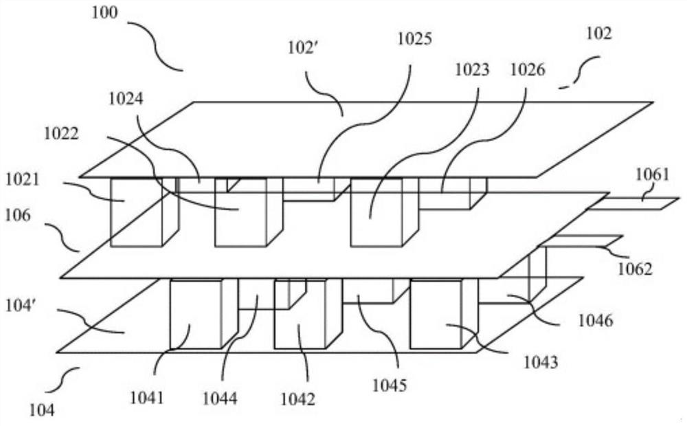
[0037] Such as figure 1 As shown, the embodiment of the present invention provides a heart rate identification device 100, and the device 100 includes:

[0038] The upper platen 102 includes an upper platen panel 102', and a plurality of vertically downward first protrusions 1021, 1022, 1023, 1024, 1025 and 1026 located on the lower side of the upper platen panel 102';

[0039] The lower backing plate 104 includes a lower backing plate panel 104' located below the upper platen 102 and parallel to the upper platen panel 102', and a plurality of vertically upward second protrusions on the upper side of the lower backing plate panel 104' 1041, 1042, 1043, 1044, 1045 and 1046;

[0040] A piezoelectric panel 106 sandwiched between the first protrusions 1021 , 1022 , 1023 , 1024 , 1025 and 1026 and the second protrusions 1041 , 1042 , 1043 , 1044 , 1045 and 1046 is also included.

[0041] The heart rate identification device 100 also includes a rubber buffer layer attached to the ...

no. 2 example

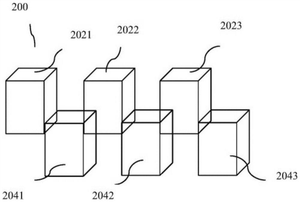
[0054] figure 2 It is a partial schematic diagram of the heart rate identification device 200 according to the second embodiment of the present invention. For descriptive purposes, figure 2 The piezoelectric panel, the upper platen panel, and the lower backing plate panel are omitted, and only the first protrusions 2021, 2022, 2023 and the second protrusions 2041, 2042, and 2043 are reserved.

[0055] As an improvement to the first embodiment, in the second embodiment, the positional relationship between the first protrusions 2021, 2022, 2023 and the second protrusions 2041, 2042 and 2043 satisfies:

[0056] When the piezoelectric panel is removed and a downward force is applied to the heart rate recognition device 200 , the first protrusions 2021 , 2022 , 2023 and the second protrusions 2041 , 2042 and 2043 can engage seamlessly. In other words, in the second embodiment, there is no gap between the orthographic projection of each first contact surface on the piezoelectric...

no. 3 example

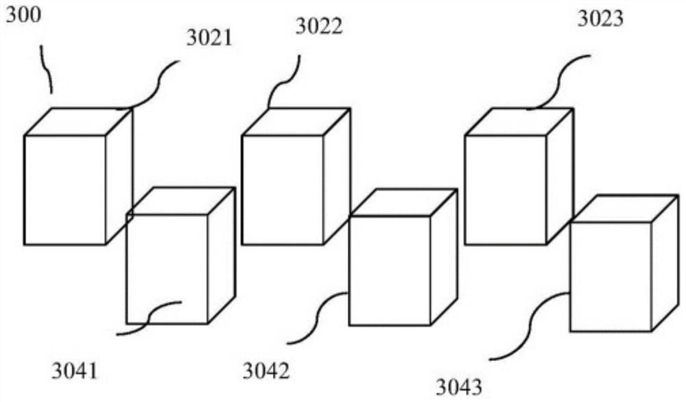
[0059] image 3 It is a partial schematic diagram of the heart rate identification device 300 according to the third embodiment of the present invention. For descriptive purposes, image 3 The piezoelectric panel, the upper platen panel, and the lower backing plate panel are omitted, and only the first protrusions 3021, 3022, 3023 and the second protrusions 3041, 3042, and 3043 are reserved.

[0060] As an improvement to the first embodiment, in the third embodiment, the positional relationship between the first protrusions 3021, 3022, 3023 and the second protrusions 3041, 3042 and 3043 satisfies:

[0061] There is a gap between the orthographic projections of the first protrusions 3021, 3022, 3023 on the piezoelectric panel and the orthographic projections of the adjacent second protrusions 3041, 3042, 3043 on the piezoelectric panel; the second protrusions 3041, There is a gap between the orthographic projections of 3042 and 3043 on the piezoelectric panel and the orthogra...


PUM


Abstract

The invention discloses a heart rate recognition device. The heart rate recognition device comprises an upper pressing plate, a lower base plate, a piezoelectric panel and a buffer layer; the upper pressing plate comprises an upper pressing plate panel and a first bulge group which is positioned on the lower side of the upper pressing plate panel and is provided with a plurality of vertically downward first bulges; the lower base plate comprises a lower base plate panel which is positioned below the upper pressing plate and is parallel to the upper pressing plate panel, and a second bulge group which is positioned on the upper side of the lower base plate panel and is provided with a plurality of vertically upward second bulges; the piezoelectric panel is clamped between the first bulge group and the second bulge group; and the buffer layer is located among the upper pressing plate, the lower base plate, and the piezoelectric panel. The heart rate recognition device has the beneficial effects that through a plurality of first contact faces and a plurality of second contact faces which are located on the upper side and the lower side of the piezoelectric panel and arranged in a staggered mode, the piezoelectric panel deforms multiple times, so that superposition of multiple electric signals is formed, the stronger electric signals can be output under the condition of bearing the same pressure, and heart rate recognition is more accurate.

Description

technical field [0001] The present invention relates to the field of signal and information processing, and more specifically, the present invention relates to a heart rate recognition device. Background technique [0002] The piezoelectric panel is a dynamic strain sensor. When the piezoelectric panel is stretched or bent, an electrical signal is generated between the upper and lower electrode surfaces of the panel. For piezoelectric panels, if the same force is applied to a large area of ​​the panel, the stress generated will be relatively small, so the signals generated between the upper and lower electrode surfaces of the panel will be relatively small. [0003] Since the piezoelectric response of the piezoelectric panel is linear over a considerable dynamic range, it can detect very small physical signals as well as sense large-scale activity. In practical applications, piezoelectric panels can be used to detect the movement of chest, legs, eye muscles and skin in the ...

Claims


Application Information

Patent Timeline
IPC IPC(8): A61B5/024
CPCA61B5/02444
Inventor 刘众王新安孙成俊卢坤涛何春舅
Owner PEKING UNIV SHENZHEN GRADUATE SCHOOL
Why Eureka
Try Eureka