Backflow tank, matching structure and electroplating production line

An electroplating production line and matching structure technology, applied in the direction of plating tank, electrolysis process, electrolysis components, etc., can solve the problems of broken guide rollers, reduce the electroplating yield of electroplating production line, affect the electroplating effect of workpieces, etc., achieve stable and safe transportation, improve electroplating Yield Effect

Pending Publication Date: 2021-05-04
KUNSHAN DONGWEI MACHINERY CO LTD
View PDF0 Cites 2 Cited by
  • Summary
  • Abstract
  • Description
  • Claims
  • Application Information

AI Technical Summary

Problems solved by technology

[0005] Therefore, the technical problem to be solved by the present invention is to overcome the prior art. When the workpiece is electroplated, the workpiece is crushed by the guide roller in the reflow tank, which aff

Method used


Image

  • Backflow tank, matching structure and electroplating production line
  • Backflow tank, matching structure and electroplating production line
  • Backflow tank, matching structure and electroplating production line

Examples


Embodiment 1

[0061] This embodiment describes a reflux tank 1, see Figure 5-Figure 9 , the backflow tank 1 includes a tank body 2 and a first plate 3, the first plate 3 is arranged in the tank body 2, and the inner cavity of the tank body 2 is divided into a first backflow cavity 4 and a plate passage 5 arranged side by side , wherein the two ends of the over-half channel along its length direction pass through the two opposite side walls on the tank body 2, and the passage through the plate 5 corresponds to the two side walls on the tank body 2 and forms first correspondingly. The inlet 6 and the first outlet 7 are used for the workpiece to pass through the passage 5, that is, the workpiece enters the passage 5 along the first inlet 6, and is transported to the first outlet 7 in the passage 5, Complete the effect by passing backflow tank 1.

[0062] In the backflow tank 1 of this structure, by setting the first plate 3 in the tank body 2, the first plate 3 divides the inner chamber of t...

Embodiment 2

[0073] This embodiment describes a matching structure with a reflow tank 1 and an electroplating tank 16, the matching structure includes at least one electroplating tank 16, the electroplating tank 16 has an electroplating cavity, and at least A reflux tank 1, the reflux tank 1 is the reflux tank 1 as recorded in embodiment 1, and the plate passage 5 of the reflux tank 1 can be communicated with the electroplating chamber sealing of the electroplating tank 16, by connecting the reflux tank 1 with the electroplating The tank 16 is cooperatingly arranged to recirculate the solution in the reflux tank 1 to the electroplating cavity of the electroplating tank 16 to maintain the liquid level in the electroplating cavity, thereby ensuring the electroplating effect of the workpiece in the electroplating tank 16 .

[0074] see Figure 10 , the number of electroplating tanks 16 can be set to two, and a reflux tank 1 is arranged on both sides of each electroplating tank 16, and the pas...

Embodiment 3

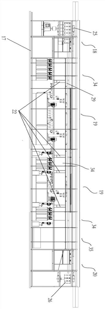
[0079] This embodiment describes a kind of electroplating production line, see Figure 1-Figure 10 , the electroplating production line includes the matching structure of at least one reflow tank 1 and the electroplating tank 16 described in Embodiment 2, and also includes a frame 17 and a conveying mechanism arranged on the frame 17, and the conveying mechanism is used to drive the workpiece along the vertical direction. Extend and move horizontally to pass through the reflow tank 1 and the electroplating tank 16 in the mating structure, on the frame 17 there are a feeding area 18 and a lowering area 20 and between the upper feeding area 18 and the lowering area 20 At least one electroplating area 19, at least one matching structure is provided in each electroplating area 19, the workpiece is loaded in the feeding area 18, and then enters the electroplating area 19 under the drive of the conveying mechanism for electroplating treatment, and then from The electroplating zone 1...


PUM


Abstract

The invention relates to the technical field of electroplating, and particularly discloses a backflow tank, a matching structure and an electroplating production line. The backflow tank comprises a tank body, a first plate is arranged in the tank body to divide an inner cavity of the tank body into a first backflow cavity and a plate passing channel which are arranged side by side, the two ends, in the length direction, of the plate passing channel penetrate through the two opposite side walls of the tank body, and a first inlet and a first outlet are correspondingly formed in the two side walls of the tank body , so that a workpiece can pass through the plate passing channel. The first plate divides the inner cavity of the tank body into the first backflow cavity and the plate passing channel which are arranged side by side, a first inlet and a first outlet of the plate passing channel penetrate through two oppositely-arranged side walls on the tank body, and when the workpiece enters the plate passing channel from a previous procedure, the workpiece can enter the plate passing channel along the first inlet and is output from the plate passing channel from the first outlet, so that the workpiece can be smoothly conveyed in the plate passing channel in the conveying process, and the breakage rate of the workpiece is reduced.

Description

technical field [0001] The invention relates to the technical field of electroplating, in particular to a reflow tank, a matching structure and an electroplating production line. Background technique [0002] Electroplating refers to the electrolytic reaction in the solution with the help of external direct current, so that the metal or alloy layer is deposited on the surface of the conductor. During electroplating, the anode of the electrode is electrically connected to the electroplating solution, and the cathode of the electrode is connected to a conductive workpiece. When the current is turned on, the positively charged cations in the solution move toward the cathode of the circuit, reducing on the surface of the workpiece to be processed, and forming an electroplating layer covering the surface of the workpiece to be processed. [0003] In the electroplating production line in the prior art, in order to keep the liquid level in the electroplating tank within a certain ...

Claims


Application Information

Patent Timeline
IPC IPC(8): C25D17/02C25D21/10C25D19/00C25D21/06
CPCC25D17/02C25D21/06C25D21/10
Inventor 韩友生方志斌袁晓波
Owner KUNSHAN DONGWEI MACHINERY CO LTD
Why Eureka
Try Eureka